POL – Polarity
Read/write command that returns/sets the input modes or input logic of various signals.
Applies to: CMD-4CR, CMD-4EX-SA
ASCII POL[axis]
Syntax:
Read:
POL[axis]
|
Where: [axis] specifies the axis to be addressed (X, Y, Z, U) |
Write:
POL[axis]=[value]
|
Where: [axis] specifies the axis to be addressed (X, Y, Z, U) [value] 17-bit value according to the chart below: |
|
Bit |
Description |
|||||
|
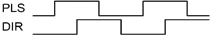
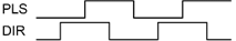
0 – 2 |
Output modes of command pulse signals |
|||||
|
Operation in the (+) direction |
Operation in the (-) direction |
|||||
|
PLS output |
DIR output |
PLS output |
DIR output |
|||
|
000 |
|
|
|
|
||
|
001 |
|
|
|
|
||
|
010 |
|
|
|
|
||
|
011 |
|
|
|
|
||
|
100 |
|
|
|
|
||
|
101 |
|
|
||||
|
110 |
|
|
||||
|
111 |
|
|
|
|
||
|
3 |
End Limit Signal (+/-L) |
0 Positive Logic |
1 Negative Logic |
|||
|
4 |
Home Logic Signal (H) |
0 Negative Logic |
1 Positive Logic |
|||
|
5 |
Alarm Signal (ALM) |
0 Negative Logic |
1 Positive Logic |
|||
|
6 |
Deceleration Signal (SD) |
0 Negative Logic |
1 Positive Logic |
|||
|
7 |
In-Position Signal (INP) |
0 Negative Logic |
1 Positive Logic |
|||
|
8 |
Deviation Counter Clear Signal (ERC) |
0 Negative Logic |
1 Positive Logic |
|||
|
9 |
Enable Axis Signal (EO) |
0 Negative Logic |
1 Positive Logic |
|||
|
10 |
Direction to Count Feedback |
0 Do Not Reverse |
1 Reverse |
|||
|
11 |
Specification of Feedback Pulse Signal |
00 x1 |
01 x2 |
|||
|
12 |
10 x4 |
11 CW/CCW |
||||
|
13 |
Z-Axis Signal |
0 Falling Edge |
1 Rising Edge |
|||
|
14 |
Direction to Count Pulse Generator Signal |
0 Do Not Reverse |
1 Reverse |
|||
|
15 |
Specification of Manual Pulse Generator |
00 x1 |
01 x2 |
|||
|
16 |
10 x4 |
11 CW/CCW |
||||


Reply:
Command is accepted and executed
Read:
Returns the input modes and input logic of various signals for the specified axis (17-bit value)
Write:
OK
Command cannot be processed
An error message is returned. See Error Codes
Example:
Read:
POLY * Returns the input modes and logic for various signal for the Y axis
Write:
POLX=4128 * Sets the input modes and logic based on the 17-bit value. Ex. 4128 converts to 1 0000 0010 0000. Using the chart above, the result is setting “PLS/DIR input,” “Alarm with Positive Logic,” and “Feedback set at x4” for the X axis.
Notes:
- Below is a link to an Excel spreadsheet Polarity of the Input/Output Logic Calculator. This calculator is to help you encode the value sent to and decode the value returned by the POL function.
See also:
System Setup, Motor Setup, Encoder Setup, Limits/Safety Setup,
ERC, ERCD, ERCP, INP, SDC, SDE, EXST, IERR, STORE
Commander Manual
2.1.6.3 Input modes and the polarity of the input/output logic