2.1.6.3 Input modes and the polarity of the input/output logic
The POL[axis] command is a 17-bit value used to set or read the input mode and/or input/output logic of various signals. Use table POL command below to see descriptions of each bit setting.
|
Bit |
Description |
|||
|
0~2 |
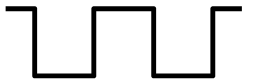
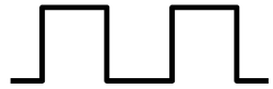
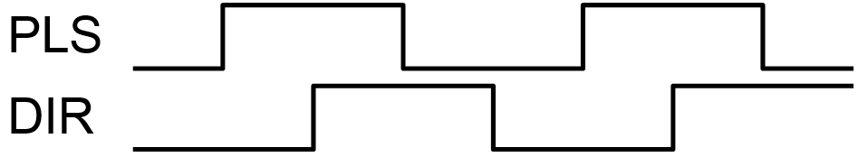
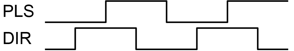
The output modes of command pulse signals |
|||
|
Positive direction operation |
Negative direction operation |
|||
|
PUL output |
DIR output |
PUL output |
DIR output |
|
|
000 |
|
|
|
|
|
001 |
|
|
|
|
|
010 |
|
|
|
|
|
011 |
|
|
|
|
|
100 |
|
|
|
|
|
101 |
|
|
||
|
110 |
|
|
||
|
111 |
|
|
|
|
|
Bit |
Description |
Setting |
||
|
3 |
Logic of End limit signal (+/-L) |
0 Positive logic |
1 Negative logic |
|
|
4 |
Logic of home signal (H) |
0 Negative logic |
1 Positive logic |
|
|
5 |
Logic of alarm signal (ALM) |
0 Negative logic |
1 Positive logic |
|
|
6 |
Logic of deceleration signal (SD) |
0 Negative logic |
1 Positive logic |
|
|
7 |
Logic of in-position (INP) |
0 Negative logic |
1 Positive logic |
|
|
8 |
Logic of deviation counter clear signal (ERC) |
0 Negative logic |
1 Positive logic |
|
|
9 |
Logic of enable signal (EO) |
0 Negative logic |
1 Positive logic |
|
|
10 |
Encoder input direction |
0 Do Not Reverse |
1 Reverse |
|
|
11~12 |
Specification of the feedback pulse signal |
00 x1 |
01 x2 |
|
|
10 x4 |
11 two pulse |
|||
|
13 |
Logic of Z-index signal |
0 Falling Edge |
1 Rising Edge |
|
|
14 |
MPG input direction |
0 Do Not Reverse |
1 Reverse |
|
|
15~16 |
Specification of the MPG input signal |
00 x1 |
01 x2 |
|
|
10 x4 |
11 two pulse |
|||


POL command
The polarity can also be set for the digital inputs, digital outputs, and configurable I/O. The DIP command can be used to toggle the polarity of the digital inputs and the DOP can be used to toggle the polarity of the digital outputs. For these 0 = Negative logic, 1 = Positive logic.
The IOP command is 2-bit and can be used to toggle the polarity of the configurable I/O. Bit 0 sets the input logic and Bit 1 sets output logic. See table IOP command below.
|
Bit |
Description |
Setting |
|
|
0 |
Logic of input setting |
0 Negative logic |
1 Positive logic |
|
1 |
Logic of output setting |
0 Negative logic |
1 Positive logic |
IOP command
< Previous SubSection | Topic Home | Home >