2.1.2.3 Encoder Inputs
 An encoder is a type of pulse generator that can be used to communicate to the Commander core the actual speed, direction, and position of the motor or system it is attached to. The Commander core accepts two different pulse types, which are set using the POL[axis](Bit11~12).
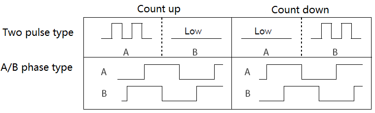
- Two pulse type (not common) is where pulses are sent to A input to count up and B input to count down. Each pulse input is one count of the encoder.
- This can be used as an up/down counter to track pulses unrelated to the motion of the motor.
- A/B phase type (common).
a. 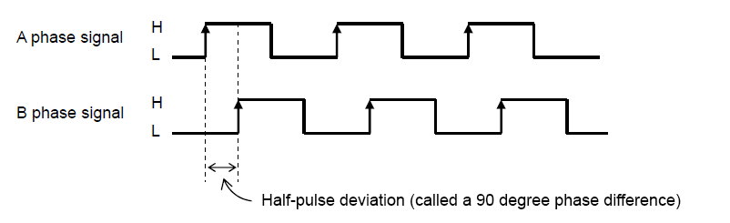 For an A/B phase type, there should be 90° difference between the pulses from A and B.
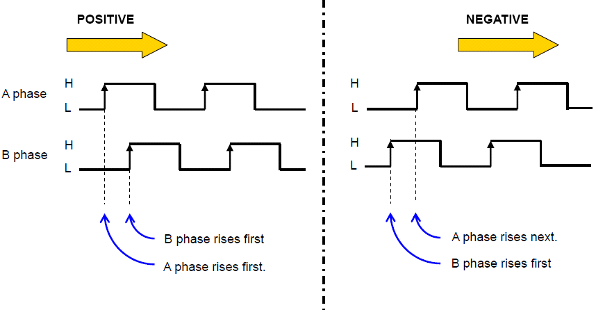
- By default, when the A phase leads the B phase motion is in the positive direction, and when B phase leads the A phase motion is in the negative direction. The direction can be changed by POL[axis](Bit10).
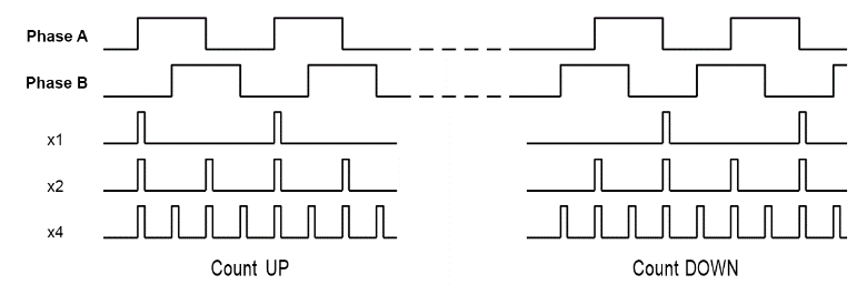
- For an A/B phase type you can select x1, x2 or x4 multiplication rate. The figure below shows how the encoder counts would be interpolated for a x1, x2, and x4 multiplication rate on a single encoder.
- x1 multiplication – Only the rising edge of the A phase is counted, B phase is not counted and is only used to check the direction of motion.
- x2 multiplication – The rising and falling edge of the A phase is counted, B phase is not counted and is only used to check the direction of motion.
- x4 multiplication – The rising and falling edge of the A and B phases are counted, and used to check the direction of motion.
Maximum frequency input on the encoder line is the maximum number of pulses that can be input to an encoder input, not the counts. Since most encoders' outputs are rated based on a x4 multiplication rate, the output frequency of pulses is most likely ¼ the published count rate output of the encoder. Please check the data sheet for your encoder to confirm.
While an encoder input is not required, there are a number of advantages to connecting one.
- Closed loop control using StepNLoop – StepNLoop is a closed-loop position verification algorithm. When the encoder is placed at the work point, it can be used to eliminate backlash in the system. When the encoder is mounted to the motor, it can help overcome missed steps. Section 2.5.3 StepNLoop Closed Loop Control operation contains more information regarding StepNLoop.
- Motor Stall detect – When an encoder is connected it is easy to detect if the motor has stalled.
- Position verification – Verify the motor has finished its move and reached the desired position.
- Z-index – the Z-index can improve your homing method. The polarity of Z-index input is set with the POL[axis](Bit13)
If an encoder is not connected or needed, the encoder inputs can be used as an up/down counter to track pulses unrelated to the motion of the motor.
|
ASCII |
|
|
Standalone |
⎯ |
< Previous SubSection | Topic Home | Home >