System Status
The Commander core allows for each device to have a unique identification number, allowing up to 64 devices to be connected to the same host. If multiple devices are connected to the host, the identification number for each device should be unique.
By default, all Commander cores are shipped from the factory with identification number 01. The current identification number of a device can be found by reading the ID command. Also, the device name will always include the current identification number. For USB communication the device name will be "CMD-4CR-xx" where xx is the identification number of the device. For serial communication, the “DeviceName” is only the identification number of the device.
In order to change the identification number of the device, first store the desired number using the ID command. Note that this value must be within the range [00-99].
For example, the command ID=02 can be sent to change the identification number to 02. To save a modified identification number to the flash memory of the device, use the STORE command. The new identification number will not take effect until after a power cycle.
The current version of firmware can be found with the VER command.
It is possible to use an external trigger to start a defined motion profile. This is done by connecting the /CSTA pins as shown in Figure 2-1. The /CSTA line needs an external pullup resistor to VDD.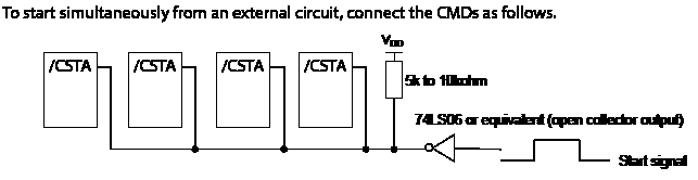
By default, the external start input is disabled (EXST=0), which will allow motion to start immediately upon receipt of any motion command. If the external start input is enabled (EXST=1) than any motion command sent will wait for the /CSTA input to go low, before motion is started. The Commander core can buffer up to 3 motions on a first-in first-out order; they will start one at a time each time the /CSTA input goes low.
The logical input of the /CSTA input cannot be changed.
|
Command |
Description |
Available with: |
Link |
|||||
|
ASCII |
Standalone |
CMD-4CR |
PMX-4EX |
PMX-4ET |
PMX-2ED |
PMX-2EX |
||
|
CLR |
ECLEAR |
Clears alarm and limit flags |
● |
● |
● |
● |
● |
|
|
DB |
|
Baud rate |
● |
● |
|
● |
● |
|
|
D |
|
StepNLoop deviation counter value |
● |
|
|
|
|
|
|
DX |
|
|
● |
● |
● |
● |
|
|
|
DN |
|
Device name |
|
● |
|
● |
● |
|
|
E |
|
Encoder value (axis) |
● |
● |
● |
● |
● |
|
|
EDEC |
|
Unique global deceleration status |
|
● |
● |
● |
● |
|
|
EP |
|
Encoder value (all) |
● |
● |
● |
|
|
|
|
ERC |
|
Deflection counter enable/disable |
● |
|
|
|
|
|
|
ERCD |
|
Error signal pulse delay |
● |
|
|
|
|
|
|
ERCP |
|
Error signal pulse width |
● |
|
|
|
|
|
|
EXST |
|
External start enable/disable |
● |
|
|
|
|
|
|
ID |
|
Commander-4CR identification number |
● |
|
|
● |
● |
|
|
IERR |
|
Ignore alarm/limit flags enable/disable |
● |
● |
● |
● |
● |
|
|
INP |
|
In-position enable/disable |
● |
|
|
|
|
|
|
LCA |
|
Global limit correction value |
|
|
|
● |
● |
|
|
MST |
MST |
Axis status acquisition |
● |
● |
● |
● |
● |
|
|
P |
P |
Pulse counter value (axis) |
● |
● |
● |
● |
● |
|
|
PE |
|
Position values for all encoders |
|
● |
● |
|
|
|
|
EP |
|
● |
|
|
|
|
||
|
POL |
|
Input and logic configuration |
● |
|
|
● |
● |
|
|
PO |
|
|
● |
● |
|
|
|
|
|
PP |
|
Pulse counter value (all) |
● |
● |
● |
|
|
|
|
PS |
PSX |
Current operation speed value |
● |
● |
● |
● |
● |
|
|
PWM |
|
Pulse width modulation duty cycle |
● |
|
|
|
|
|
|
REG |
|
Registers |
● |
|
|
|
|
|
|
SDC |
|
Slow down deceleration signal configuration |
● |
|
|
|
|
|
|
SDE |
|
Slow down deceleration signal enable/disable |
● |
|
|
|
|
|
|
STORE |
|
Save system configuration settings to flash memory |
● |
● |
● |
● |
● |
|
|
VER |
|
Returned firmware version number |
● |
● |
● |
● |
● |
|