2.1.3.2.2 High-Speed Digital Output
The Commander core provides four (4) high-speed outputs. Each output can independently be set as a synchronization output or a general-purpose output. By default, the outputs are set to general-purpose outputs.
Synchronization Outputs
The Commander core provides four high-speed synchronization outputs. This feature allows the controller to perform a high-speed comparison between the encoder or pulse position counter and a set condition (comparator), which is set with the SYNP[axis] command. When the condition is met, the corresponding synchronization output is enabled. The timing between the condition being met and the synchronization output being triggered is 150 to 200ns.
There are three modes for the synchronization outputs to be enabled, which can be set with the SYNC[axis] command:
- At position mode (counter = comparator)
- > or < position mode (counter is either > or < than the comparator)
- Continuous mode (every comparator position)
For continuous mode, and at position mode, the output can be output in both directions, or limited to only one direction (positive or negative) of movement.
For > or < position mode, you can select only Counter > Comparator or Counter < Comparator.
|
Bit |
Description |
Decimal |
||
|
Pulse Position |
Encoder Position |
|||
|
0-3 |
Synchronization Condition: |
From sync source: |
||
|
0001 |
Trigger when sync position = actual position. Any direction |
1 |
17 |
|
|
0010 |
Trigger when sync position = actual position. Positive motion |
2 |
18 |
|
|
0011 |
Trigger when sync position = actual position. Negative motion |
3 |
19 |
|
|
0100 |
Trigger when sync position > actual position |
4 |
20 |
|
|
0101 |
Trigger when sync position < actual position |
5 |
21 |
|
|
0111 |
Reserved/not available |
|
|
|
|
1000 |
Trigger every sync position. Any direction |
8 |
24 |
|
|
1001 |
Trigger every sync position. Positive motion |
9 |
25 |
|
|
1010 |
Trigger every sync position. Negative motion |
10 |
26 |
|
|
4 |
Synchronization Source: |
|
|
|
|
0 |
Sync position will be compared to pulse position |
|
|
|
|
1 |
Sync position will be compared to encoder position |
|
|
|
Synchronization mode and source (SYNC)
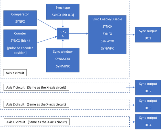
Block Diagram of synchronization function
Each axis has a designated high-speed synchronization output. While synchronization output is enabled for an axis, the corresponding digital output cannot be manually controlled by the user. See corresponding synchronization output for each axis in table synchronization output below.
|
Axis |
Output |
|
X |
DO1/SYNCx |
|
Y |
DO2/SYNCy |
|
Z |
DO3/SYNCz |
|
U |
DO4/SYNCu |
Synchronization output
Use the SYNO[axis] command to enable and the SYNF[axis] command to disable the synchronization feature. To read the synchronization status, use the synchronization status SYNS[axis] command (2-bit).
|
Bit |
Condition |
Setting |
|
|
0 |
Synchronization function |
0 - Disabled |
1 - Enabled |
|
1 |
Synchronization Window |
0 - Disabled |
1 - Enabled |
SYNS command return
In continuous mode, there is an option for a synchronization window function. When enabled with the SYNWO[axis] command, the synchronization function will run continuously, but only outputs a pulse when the counter is between the synchronization maximum SYNMAX[axis] and minimum SYNMIN[axis] points. There is no loss of synchronization when outside the synchronization window while continuous mode is enabled. To disable the window function, use the SYNWF[axis] command; synchronization will not be lost. To simultaneously disable the window function and continuous sync mode, use the SYNF[axis] command.
The DOP can be used to toggle the polarity of the digital outputs.
|
ASCII |
|||||
|
Standalone |
SYNON[axis] |
⎯ |
SYNOFF[axis] |
⎯ |
SYNSTAT[axis] |
|
ASCII |
|||||
|
Standalone |
SYNPOS[axis] |
SYNCFG[axis] |
⎯ |
⎯ |
⎯ |
< Previous SubSection | Topic Home | Home >
High-Speed Digital Outputs
Any of the four high-speed outputs can be set independently to be general-purpose outputs by disabling the synchronization feature using the SYNF[axis] command for the corresponding axis. These outputs are set to general-purpose by default.
The 4-bit DO command can be used to set all the digital outputs at once. The DO value is a decimal number and must be within the range of 0-15.
Digital outputs can also be set one at a time with the DO[1-4] commands. Note that the indexes are 1-based for the bit references. For example, DO1 refers to bit 0, not bit 1. See table DO command below for details.
|
Bit |
Output |
Bit-Wise Command |
|
0 |
Digital Output 1 |
DO1 |
|
1 |
Digital Output 2 |
DO2 |
|
2 |
Digital Output 3 |
DO3 |
|
3 |
Digital Output 4 |
DO4 |
Table DO command
If a digital output is turned on, the corresponding bit of the DO command is 1. Otherwise, the bit status is 0. The voltage level of the digital output when it is on or off is determined by the polarity setting. The DOP command can be used to toggle the polarity of the digital outputs.
The initial state of the digital outputs can be defined by setting the 4-bit DOBOOT register to the desired initial digital output value. The DOBOOT value must be within the range of 0-15. The value is stored to flash memory once the STORE command is issued.
|
Bit |
Output |
Setting |
|
0 |
Digital Output 1 |
0 - OFF 1 - ON |
|
1 |
Digital Output 2 |
0 - OFF 1 - ON |
|
2 |
Digital Output 3 |
0 - OFF 1 - ON |
|
3 |
Digital Output 4 |
0 - OFF 1 - ON |
Table DOBOOT command
< Previous SubSection | Topic Home | Home >