Joystick
Joystick control is available on the Commander core for the X and Y-axis. When this mode is enabled, the pulse speed and direction output for the X and Y axis can be controlled by their corresponding analog input. See the axis to analog input assignment in the table below.
|
Axis |
Analog Input |
|
X |
AI1 |
|
Y |
AI2 |
To enable or disable joystick control for an axis, use the ASCII command JENA or the standalone command JOYENA.
For the Commander core to properly translate the analog inputs into a safe pulse speed and direction output for your system, you first must define what is acceptable and safe for your system. This includes defining the relation between voltage and direction of travel, and the zero-tolerance (or dead) zone during which there is no output from the Commander core. The safe speeds are defined as the maximum speed the analog input can command and maximum rate of speed change. The joystick positioning soft limits define where the analog inputs can command a system to move.
Direction control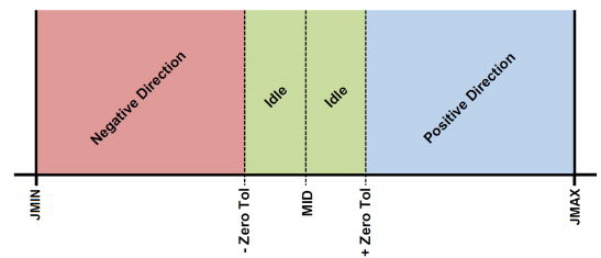
The JMAX[axis] command can be used to define the maximum analog input value for the specified axis. Similarly, the JMIN[axis] command can be used to define the minimum analog input value for the specified axis. MID represents the zero-joystick position. There is no command corresponding to MID. This is an internally calculated value using the following formula:

During joystick operation, analog input of JMIN[axis] to MID represents negative joystick direction and analog input of MID to JMAX[axis] represents positive joystick direction. Setting the value of JMAX[axis] to be less than the value of JMIN[axis] will result in a change of direction polarity during joystick operation.
The ASCII command JTOL[axis] can be used to define the zero-tolerance (or dead) zone around the MID value. No movement will occur while the analog input value is within the zero-tolerance zone. The zero-tolerance parameter will be on the positive and negative side of the MID point to define to the zero-tolerance zone. See the figure to the right for details.
Speed control
The maximum joystick speed for the X and Y-axes is set using the ASCII command JSPD[axis]. For standalone mode, the JOYHS[axis] command should be used. This parameter will define the speed of the specified axis at the maximum and minimum analog input values.
The maximum allowable speed change (delta) for the X and Y axes is set using the ASCII command JDEL[axis]. For standalone mode, the JOYDEL[axis] command is used. This parameter will control the acceleration/deceleration of the specified axis while the joystick mode is enabled.
Position control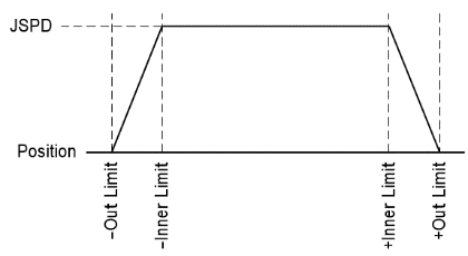
Joystick control also has soft limits, which are defined by a negative outer limit, negative inner limit, positive inner limit, and a positive outer limit, using the JLIM[number] command.
When moving in a positive direction, as soon as the positive inner limit is crossed, the speed is reduced. Speed will continue to decline as the position moves closer to the outer limit value. If the position reaches the positive outer limit, the joystick speed is set to zero and movement in the positive direction is prohibited. The same behavior is applicable to the negative direction and negative limits. The figure to the right represents the relationship between the joystick speed and inner and outer limits.
|
Command |
Description |
Available with: |
Link |
|||||
|
ASCII |
Standalone |
CMD-4CR |
|
|
|
|
||
|
AI |
|
Analog Input |
● |
|
|
|
|
|
|
JDEL |
|
Joystick speed delta |
● |
|
|
|
|
|
|
JENA |
JOYENA |
Joystick enable/disable |
● |
|
|
|
|
|
|
JE |
|
|
|
|
|
|
|
|
|
JF |
|
|
|
|
|
|
|
|
|
JO |
|
|
|
|
|
|
|
|
|
JLIM |
|
Joystick limits |
● |
|
|
|
|
|
|
JL |
|
|
|
|
|
|
|
|
|
JMAX |
|
Joystick maximum voltage setting |
● |
|
|
|
|
|
|
JMIN |
|
Joystick minimum voltage setting |
● |
|
|
|
|
|
|
JSPD |
JOYHS |
Joystick maximum speed setting |
● |
|
|
|
|
|
|
JTOL |
|
Joystick dead band range |
● |
|
|
|
|
|
|
JV |
|
Joystick speed, delta, and tolerance configuration |
|
|
|
|
|
|
The black dots indicate the command is available on the listed controller family.