2.5.2.2 Electronic gearing the MPG signal
After the input mode stage, the MPG pulse signal is converted to counts based on the POL[axis] settings. The counts then pass through an electronic gearing stage, which includes a multiplier MPM[axis] and divider MPD[axis] circuit.
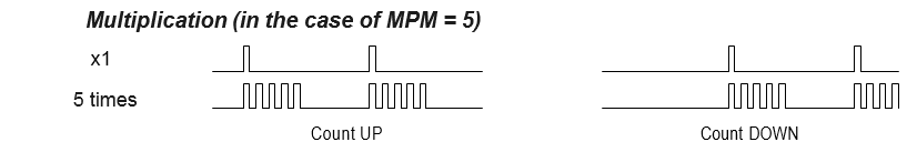
MPM[axis] can be used to access the multiplier. The multiplier can be set to a value from [1 to 32]. A value of 1 will turn off the multiplier.
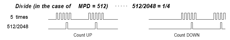
MPD[axis] is the numerator of the divider circuit. The MPD[axis] can be set to a value from [1 to 2048]. The denominator of the divider circuit is fixed as 2048. A value of 2048 will turn the divider off.
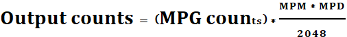
The multiplier and divider circuits can be used together to create any ratio. The multiplier and divider use the following equation to determine the number of output counts*:
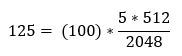
Example: Final ratio that is needed is 100 pulses-in and 125 pulses-out (1.25). By setting MPM[axis] to 5, then the input of 100 pulses is 500. since 500/4 = 125 MPD[axis] = 512 (512/2048 = ¼) the output pulses will be 125.
MP[axis] can be written to set an MPG position or read to see the current position. The counter value here is the final counts after the electronic gearing stage.
Footnote:
* MPG counts are counts after the input mode setup done by POL[axis].
< Previous SubSection | Topic Home | Home | Next SubSection >