
3.3 Recommended PCB Footprint
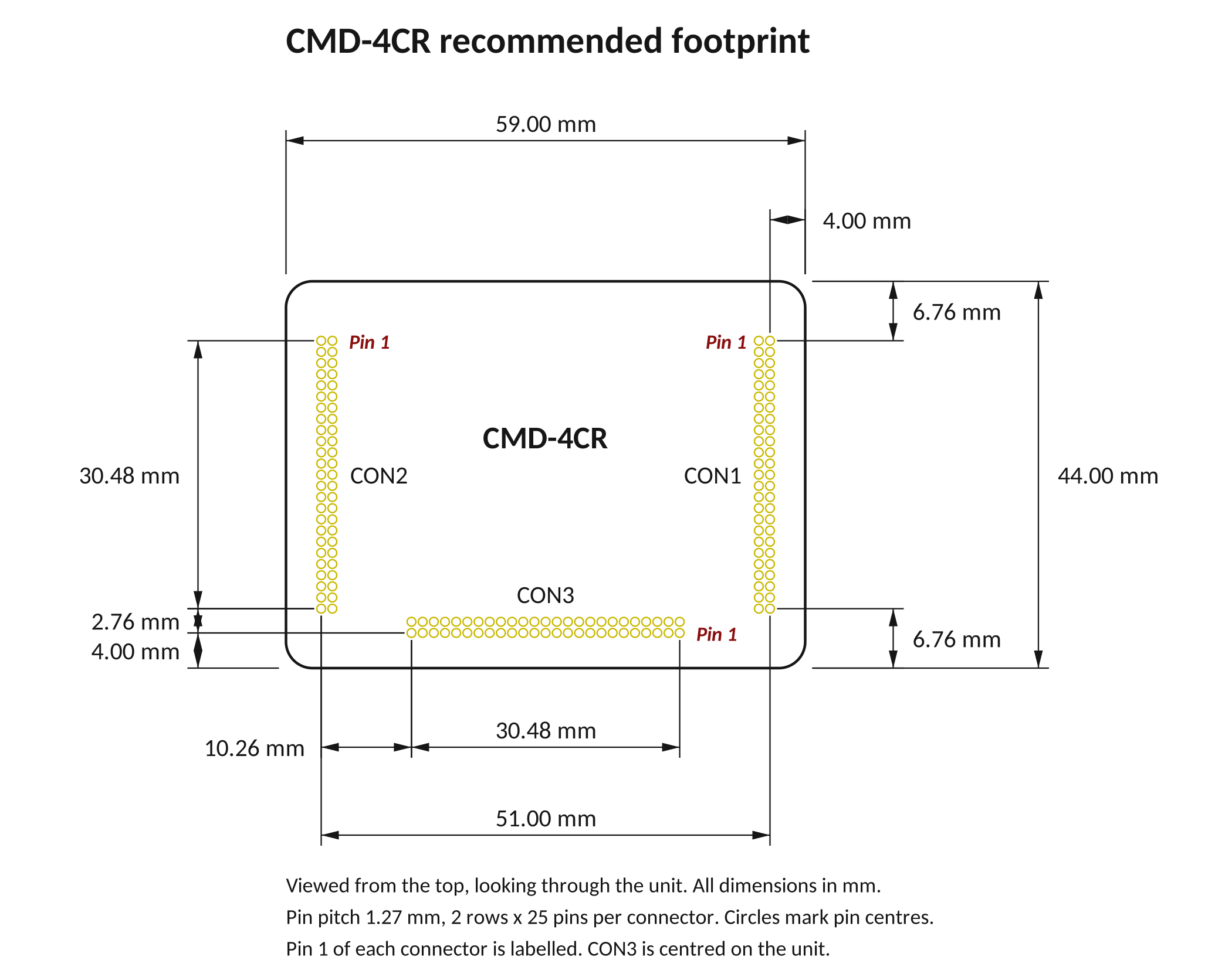
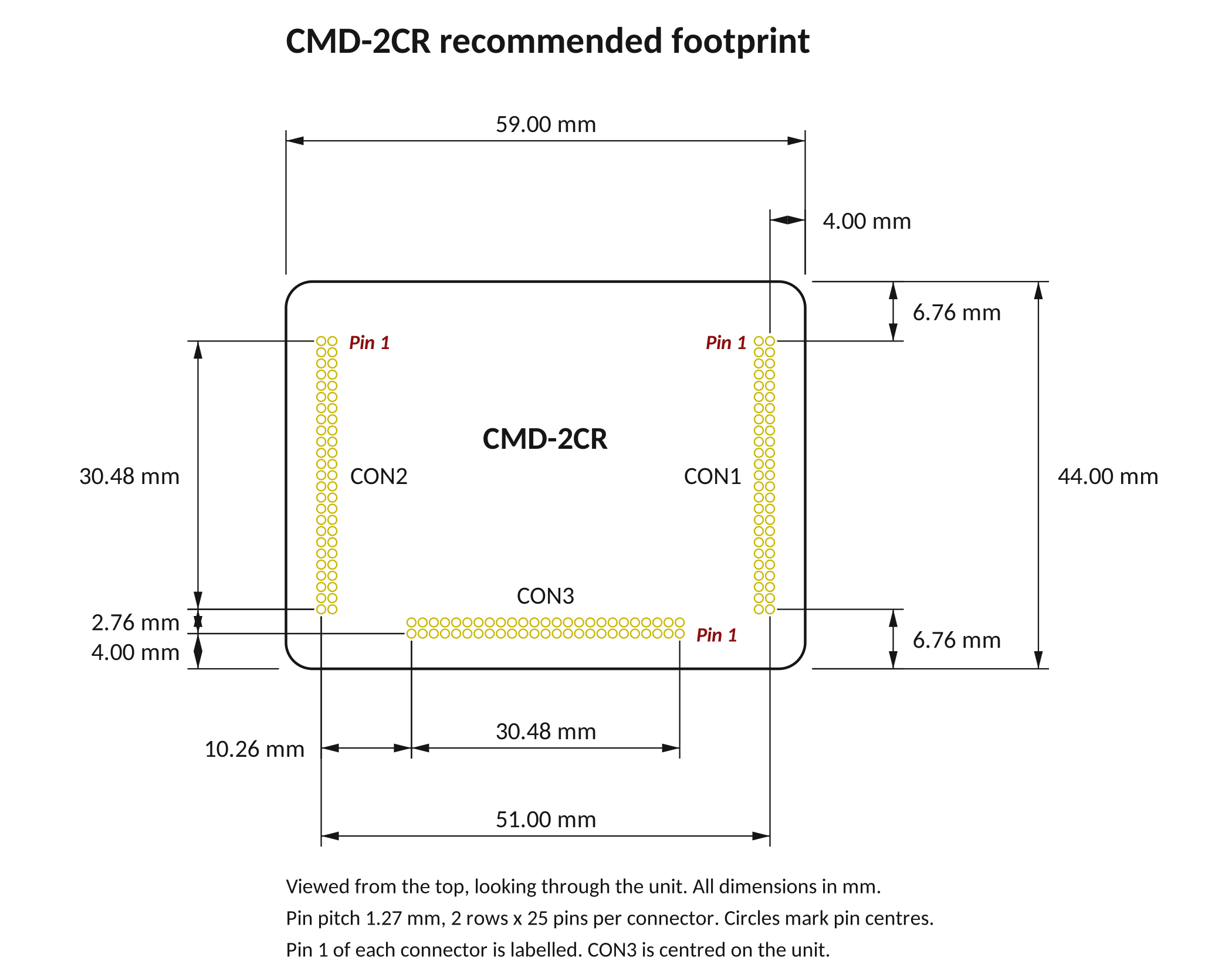
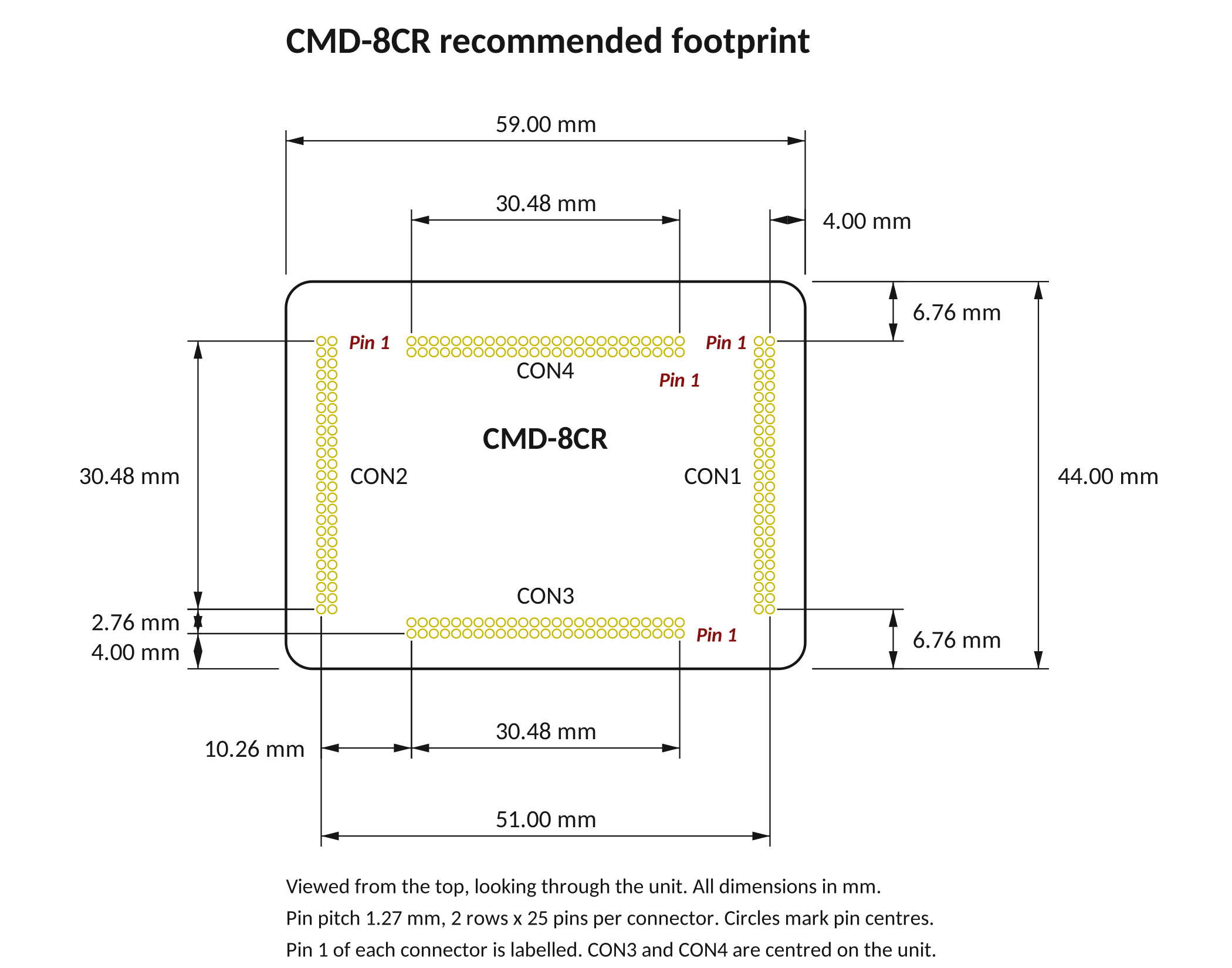
This section shows the recommended footprint for the board that the Commander core plugs into, for each model. Use it to lay out your PCB so the connectors line up.
Viewing direction
The footprint images are drawn as if you were looking down from the top and could see through the unit, the same view as the pinout diagrams. They are not the underside view used on the Connectivity page. If you compare the two, left and right are reversed.
Footprints by model
EDM Symbol/Footprint/3D packages
The links below downloads a package containing everything you need to design the CMD-4CR into your own PCB: schematic symbols, PCB footprints (surface-mount and through-hole), 3D models, an Eagle / Fusion library, neutral drawings and two KiCad example projects. It is free to use for personal and commercial work. Read the included Readme file for insturctions on how to use.
< Section Home | Home | Next SubSection >