
3.4 3D CAD Models
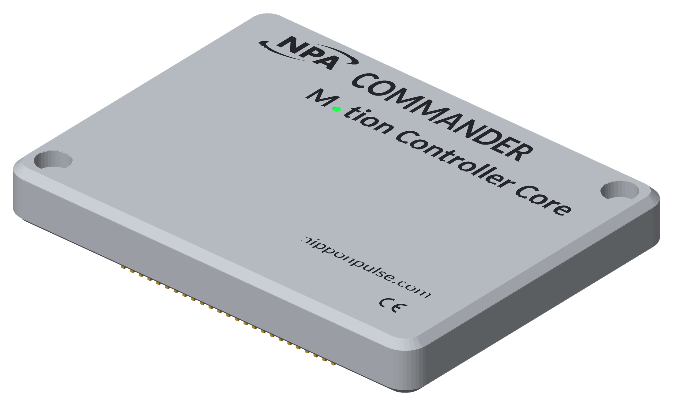 Use these 3D models to check fit and clearance when you design the Commander core into your product. Models are provided for the CMD-2CR / CMD-4CR (both units share the same shape) and the CMD-8CR.
What the models show
- The outside of the unit, including the engraved text, logo and CE mark.
- The LED hole, shown in green as if the LED is lit.
- The connector pins (CON1 to CON3 on the CMD-2CR/CMD-4CR, CON1 to CON4 on the CMD-8CR).
- Internal board parts are left out to keep the files small.
Orientation and units
- Units are millimeters.
- The cover is facing up (+Z). The origin is the center of the unit.
- Z = 0 is the bottom face of the base plate. The connector pins extend below it to Z = -2.70 mm (±0.1 mm).
- The model uses the same top-down view as the pinout diagrams and the Recommended PCB Footprint, so the connectors line up with the footprint.
File formats
STEP (.step, .stp) works with most CAD programs and keeps the colors. Other formats are available if your software needs them: [list to be confirmed].
These models are for design reference. Dimensions are ±0.1 mm. Use the dimensional drawings for the official dimensions.
Downloads:
STEP
All formats (zip)
< Previous Chapter | Topic Home | Home | Next Topic >