
3.7 Linear Shaft Motor Data Setup
In these examples, Axis C is used for demonstration.
In your environment, configure the axis that corresponds to your specific wiring and system layout. Always refer to the actual datasheet of your motor model when entering parameters.
Complete all steps on this page before proceeding to the next topic.
On this page
1. Open the Motor Data Screen
- After completing the amplifier setup, open the Motor Data screen for the selected axis.
- Select Use Specification Data to manually enter the motor parameters.
Important: Verify All Motor Specifications Before Calculating Settings.
The calculated amplifier parameters are based entirely on the motor data entered on this screen. Before clicking the Calculator icon, verify all motor specifications against the motor datasheet, including:
- Electrical Cycle Length
- Peak Force
- Continuous Force
- Force Constant
- Back EMF Constant
- Resistance
- Inductance
Verify that the units shown in the software match the units specified in the motor datasheet. Pay particular attention to current and force ratings, as some specifications may be listed as Peak values while others may be listed as RMS values.
Incorrect motor data or unit selection may result in improper current limits, unstable tuning, poor performance, or unexpected motor behavior.
Always confirm the entered values before proceeding with automatic parameter calculation.
2. Enter Motor Specifications
- General Information
- Manufacturer: e.g., NPM
- Model: e.g., S060T 100st_sample
- Units: Metric or English (select according to your datasheet)
- Motor Characteristics
- Electrical Cycle Length: e.g., 24 mm
- Mass: e.g., 0.2 kg
- Peak Force: e.g., 7.08 N
- Continuous Force: e.g., 1.77 N
- Velocity Limit: e.g., 500 mm/s
- Electrical Parameters
- Force Constant: e.g., 1.77 N/Arms
- Back EMF Constant: e.g., 1.77 V/m/s
- Resistance: e.g., 2.9 Ω
- Inductance: e.g., 0.25 mH
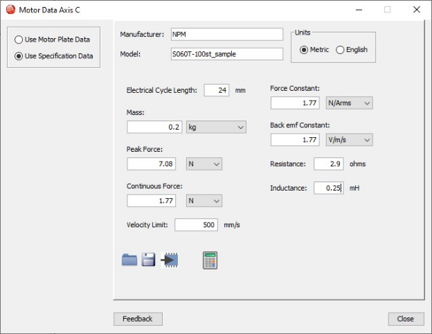
Once all parameters are entered, proceed to the calculation step.
3. Auto Calculate Settings
Click the Calculator icon.
The software calculates the internal amplifier settings based on the motor’s electrical and force characteristics.
A popup window shows the computed parameters:
- Current Loop Cp / Ci Gains
- Peak & Continuous Current Limits
- I‑Loop and V‑Loop filter settings
- Velocity loop gains
- Acceleration / deceleration limits
- Additional control parameters
These values are automatically generated based on the motor data you entered.
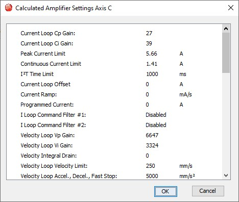
Click OK to continue.
4. Save Motor Data to Flash
After closing the calculated settings window, a message pops up:
Only motor data has been saved to flash.
Amplifier settings must be saved to flash after verification.
This confirms:
- Motor data has been written to flash
- Amplifier settings still need to be saved separately
Click OK.
Continue to Linear Shaft Motor Tuning -->