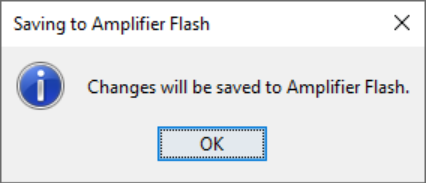
3.6 Linear Shaft Motor Setup
In these examples, Axis‑C is used for demonstration.
In your environment, configure the axis that corresponds to your specific wiring and system layout.
Complete all steps on this page before proceeding to the next topic.
On this page
- Amplifier Setup
- Select Motor Family and Motor Type
- Configure Feedback Options
- Motor Feedback Resolution
- Encoder Error Filter
- Brake/Stop Settings
- Operating Mode Options
- Miscellaneous Options
Open the Amplifier Setup menu and configure the basic drive parameters for your selected axis.
This includes:
- Motor family selection
- Motor type (Linear / Rotary)
- Feedback device configuration
- Commutation method
- Operating mode
- Safety and limit settings
- Motor Data Configuration
After the amplifier setup is complete:
- Enter the motor's electrical characteristics
- Input the linear scale or encoder resolution
- Specify phase resistance, inductance, rated current, rated force (if available)
- Select the appropriate commutation offset or run the built‑in commutation tools
For linear motors, proper motor data is essential for stable current control and accurate servo operation.
- Gain Tuning (I Loop, V Loop, P Loop)
Tune the closed-loop gains:
- Current Loop (I Loop):
Typically tuned using Auto Tune, similar to the stepper motor configuration. - Velocity Loop (V Loop):
Adjust the velocity response, damping ratio, and bandwidth. - Position Loop (P Loop):
Tune the proportional gain and filters to achieve stable and precise motion.
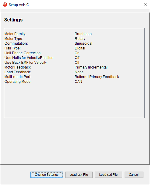
- Review Current Settings
The initial page displays the amplifier’s currently programmed configuration, including motor family, commutation mode, feedback type, and operating mode. - Click Change Settings to modify the parameters.
2. Select Motor Family and Motor Type
- On the Motor Options page:
- Set Motor Family to Brushless
- Set Motor Type to Linear
These selections configure the drive for a brushless linear servo motor.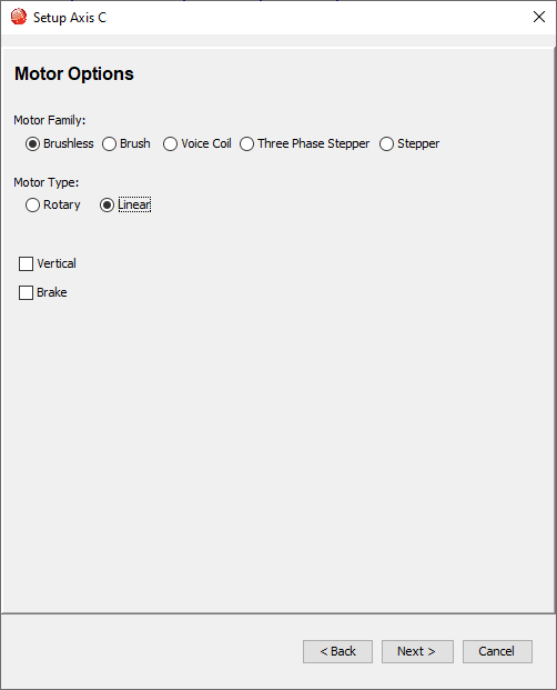
- Click Next.
- On the Feedback Options page:
- Hall Type: None
- Motor Feedback: Incremental
- Input Source: Primary
- Load Feedback: None
These settings correspond to a linear motor using an incremental scale or encoder.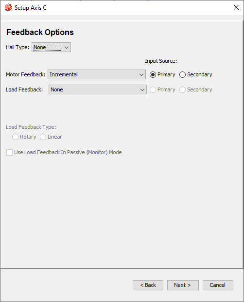
- Click Next.
Important: Verify the encoder or linear scale resolution before proceeding.
Entering incorrect feedback resolution causes position errors, incorrect travel distances, and tuning problems.
Always confirm the resolution value from the encoder or scale datasheet.
- Enter the resolution of the linear encoder:
- Example: 0.1 mm per count
- Select units (mm or µm) according to your encoder specification
- Leave No Encoder Loss Detection selected unless encoder fault monitoring is required.
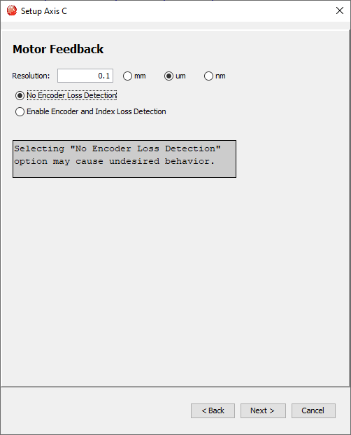
- Click Next.
No changes are required on this page.
Leave all parameters at 0 (default values).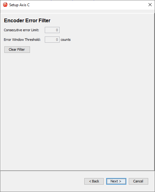
Click Next.
Linear motors typically do not require brake control.
Leave all parameters:
- Brake/Stop Delay Time = 0 ms
- Brake/Stop Activation Velocity = 0 mm/s
- PWM Delay Brake/Stop Response Time = 0 ms
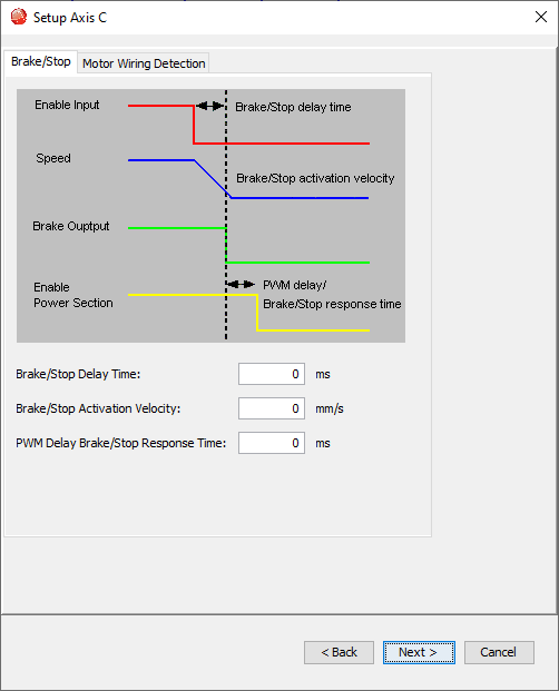
Click Next.
Configure the operating behavior:
- Operating Mode: Position
- Command Source: Digital Input
- Digital Input Source: High Speed Inputs
This allows the linear motor to receive position commands through external pulse signals or digital commands.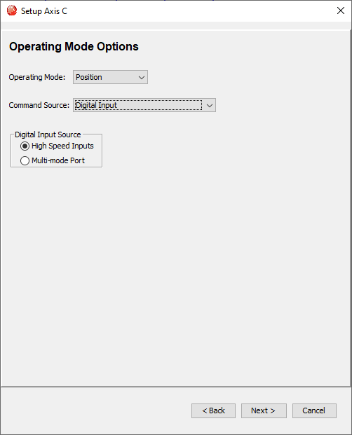
Click Next.
On the final settings page:
- Commutation Mode: Sinusoidal
- Multi‑mode Port: Differential Input
- Simulated Encoder Output Counts: 4000 counts/rev (leave default unless required)
- Count Divide: None
- Output frequency settings may remain at default.
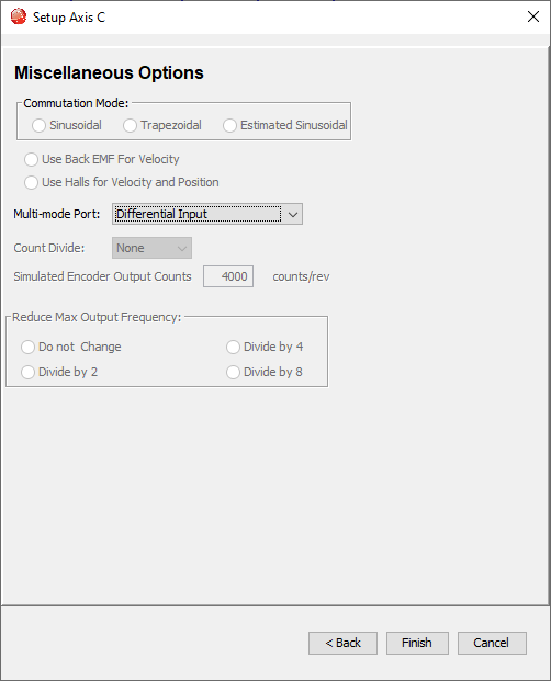
Click Finish to complete amplifier setup.