
3.2 IO Setup
Complete all steps on this page before proceeding to the next topic.
On this page
- Open the Input/Output Configuration Window
- Assign Digital Inputs for All Axes
- Save Updated IO Settings
1. Open the Input/Output Configuration Window
- Navigate to the CME control screen.
- Click Input/Output to open the Motor Configuration Window.
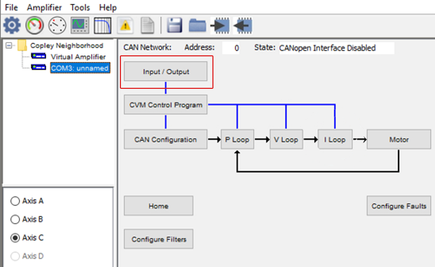
The I/O Configuration Window opens, allowing you to assign and customize digital input and output functions.
2. Assign Digital Inputs for All Axes
When configuring digital inputs, assign each group according to your system layout:
- IN1 – IN6 → Axis A
- IN7 – IN12 → Axis B
- IN13 – IN18 → Axis C
Note: The example image shows only IN1–IN12. Configure IN13–IN18 for Axis C using the same method and pattern used for Axis A and Axis B.
Verify and update each input:
- Select the correct input function.
- Set debounce, if required.
- Choose the appropriate axis routing (Axis A / Axis B / Axis C).
- Confirm the polarity (Hi / Lo).
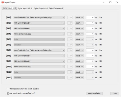
Note: The example image shows only IN1–IN12. Configure IN13–IN18 for Axis C using the same method and pattern used for Axis A and Axis B. - Repeat process until all digital inputs (IN1–IN18) are correctly assigned.
3. Save Updated I/O Settings to Amplifier Flash
After making changes, save the updated configuration to flash memory to ensure settings persist after power cycling.
Save settings:
- Click the Download to Amplifier / Save to Flash icon to download the configuration from your PC to the amplifier.
- Click OK on the confirmation message to save to flash.
Important: If you do not save to flash, all I/O changes are lost when the drive is rebooted.