
3.10 Velocity Loop (V Loop) Tuning
Complete all steps on this page before proceeding to the next topic.
On this page
1. Configure the Function Generator for Velocity Tuning
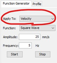
In the Scope Axis C window, locate the Function Generator panel on the left side.
Configuration:
- Apply To: Velocity
- Function: Square Wave
- Amplitude: 25 mm/s (example shown in your image)
- Frequency: 5 Hz
These values define the excitation signal used to test the Velocity Loop response.

2. Enable AutoSetup for Automatic Channel Assignment
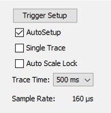
On the Trigger Setup section, select the Check AutoSetup box.
When AutoSetup is enabled, the Scope automatically assigns the appropriate measurement channels.
The Settings section indicates:
- Pink trace: Commanded Velocity
- Blue trace: Actual Velocity (feedback)
This ensures the correct signals are plotted without needing manual channel selection.

3. Start the Velocity Loop Test
Press the Start button in the Function Generator section.
The amplifier:
- Applies a velocity square‑wave command
- Drives the motor back and forth at 5 Hz
- Begins capturing the commanded (pink) and actual (blue) velocity response
The graph at the top updates in real time.
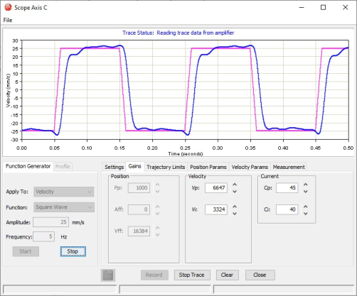

A good Velocity Loop shows:
- Actual velocity (blue) closely following commanded velocity (pink)
- Low overshoot
- No oscillation or ringing
- Smooth transitions between high and low velocity
A poorly tuned loop shows:
- Oscillation
- Large overshoot
- Delay before tracking the pink line
- Ripple or unstable behavior
- Excessive overshoot
- Slow response
- Poor tracking accuracy
- Velocity response that does not reach the commanded value
These conditions may indicate that additional Vp and/or Vi tuning is required.
Continue to Position (P Loop) Tuning -->