CMD-4EX-SA Standalone Version
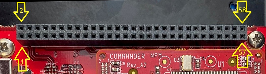
J7 is an 58-pin connector used to pass signals up to various top boards. These signals are either unused (TBS does not take pins 1, 2, 53-58) or go to a top board. These 58 pins are not designed to touch the outside world directly, so no additional protection is present. Pins 53 to 58 are general IO pins, and are protected the same way that all other IO pins are.
Pin description:
|
Pin # |
In/Out |
Name |
Description |
I/F circuit |
|
1 |
I/O |
D+ |
D+ differential data signal |
|
|
2 |
I/O |
D- |
D- differential data signal |
|
|
3 |
O |
PULx |
Pulse [X Axis] |
|
|
4 |
O |
DIRx |
Direction [X Axis] |
|
|
5 |
I |
+Lx |
+Limit [X Axis] |
|
|
6 |
I |
-Lx |
-Limit [X Axis] |
|
|
7 |
I |
Hx |
Home [X Axis] |
|
|
8 |
I |
INPx |
In-Position [X Axis] |
|
|
9 |
O |
EOx |
Enable [X Axis] |
|
|
10 |
I |
EAx |
A Channel Encoder Input [X Axis] |
|
|
11 |
I |
EBx |
B Channel Encoder Input [X Axis] |
|
|
12 |
I |
EZx |
Z Index Encoder Input [X Axis] |
|
|
13 |
I |
ALMx |
Servo Alarm [X Axis] |
|
|
14 |
O |
ERCx |
Error Clear [X Axis] |
|
|
15 |
O |
PULy |
Pulse [Y Axis] |
|
|
16 |
O |
DIRy |
Direction [Y Axis] |
|
|
17 |
I |
+Ly |
+Limit [Y Axis] |
|
|
18 |
I |
-Ly |
-Limit [Y Axis] |
|
|
19 |
I |
Hy |
Home [Y Axis] |
|
|
20 |
I |
INPy |
In-Position [Y Axis] |
|
|
21 |
O |
EOy |
Enable [Y Axis] |
|
|
22 |
I |
EAy |
A Channel Encoder Input [Y Axis] |
|
|
23 |
I |
EBy |
B Channel Encoder Input [Y Axis] |
|
|
24 |
I |
EZy |
Z Index Encoder Input [Y Axis] |
|
|
25 |
I |
ALMy |
Servo Alarm [Y Axis] |
|
|
26 |
O |
ERCy |
Error Clear [Y Axis] |
|
|
27 |
O |
PULz |
Pulse [Z Axis] |
|
|
28 |
O |
DIRz |
Direction [Z Axis] |
|
|
29 |
I |
+Lz |
+Limit [Z Axis] |
|
|
30 |
I |
-Lz |
-Limit [Z Axis] |
|
|
31 |
I |
Hz |
Home [Z Axis] |
|
|
32 |
I |
INPz |
In-Position [Z Axis] |
|
|
33 |
O |
EOz |
Enable [Z Axis] |
|
|
34 |
I |
EAz |
A Channel Encoder Input [Z Axis] |
|
|
35 |
I |
EBz |
B Channel Encoder Input [Z Axis] |
|
|
36 |
I |
EZz |
Z Index Encoder Input [Z Axis] |
|
|
37 |
I |
ALMz |
Servo Alarm [Z Axis] |
|
|
38 |
O |
ERCz |
Error Clear [Z Axis] |
|
|
39 |
O |
PULu |
Pulse [U Axis] |
|
|
40 |
O |
DIRu |
Direction [U Axis] |
|
|
41 |
I |
+Lu |
+Limit [U Axis] |
|
|
42 |
I |
-Lu |
-Limit [U Axis] |
|
|
43 |
I |
Hu |
Home [U Axis] |
|
|
44 |
I |
INPu |
In-Position [U Axis] |
|
|
45 |
O |
EOu |
Enable [U Axis] |
|
|
46 |
I |
EAu |
A Channel Encoder Input [U Axis] |
|
|
47 |
I |
EBu |
B Channel Encoder Input [U Axis] |
|
|
48 |
I |
EZu |
Z Index Encoder Input [U Axis] |
|
|
49 |
I |
ALMu |
Servo Alarm [U Axis] |
|
|
50 |
O |
ERCu |
Error Clear [U Axis] |
|
|
51 |
O |
VCC |
Power Output +5 VDC @ 250mA |
|
|
52 |
O |
GND |
Ground |
|
|
53 |
I/O |
IO27 |
General-purpose, configurable I/O 27 |
|
|
54 |
I/O |
IO28 |
General-purpose, configurable I/O 28 |
|
|
55 |
I/O |
IO29 |
General-purpose, configurable I/O 29 |
|
|
56 |
I/O |
IO30 |
General-purpose, configurable I/O 30 |
|
|
57 |
I/O |
IO31 |
General-purpose, configurable I/O 31 |
|
|
58 |
I/O |
IO32 |
General-purpose, configurable I/O 32 |
Mating Connector
Description: 58 pin 0.1” (2.54mm) header
Manufacturer: Samtec, Inc.
Manufacturer Part: TSW-129
Note: Other 2.54mm compatible headers can be used. Length of pin will be dependent on your application.