
6.1 Hardware
Hardware Differences
This page is currently under development. As the release of the CMD-2ED-SA gets closer this page will be updated with the most current information.
The CMD-2ED-SA was designed to be drop-in compatible with the PMX-2ED-SA
The enclosure style of the CMD-2ED-SA, are very close to the enclosures used of the PMX-2ED-SA. The CMD-2ED-SA are also pin to pin compatible to the PMX-2ED-SA. In most cases, no changes to mounting and connector locations, panel cutouts, brackets, or cable harnesses will be necessary.
Some new features are using pins which were labeled N/C in the PMX-2ED-SA. Please review the manual before connecting the CMD-2ED-SA to your system.
Stepper Motor Drivers:
The CMD-2ED-SA uses a more advanced stepper motor driver, Toshiba TB67S128FTG, which adds these features:
- Motor Axis power LED and Enable LED added.
- Microstepping can be set (full to 1/8) with jumpers on PCB for backwards compatiblity. If no microstepping jumpers are installed, microstepping (full to 1/128) can be set in the softwere and changed on-the-fly.
- Jumper set current setting adjusted to match stepper motors from Nippon Pulse.
- ON PCB Potentiometer added for custom current setting adjustment.
- Position latching inputs were added to pin 20 (Latch X-axis) and pin 24 (Latch Y-axis) of the 50-Pin Connector Control/Encoder IO connector.
Dimensions and mounting
The CMD-2ED-SA uses the same enclosure, cover and base as the PMX-2ED-SA. The outside dimensions, the four Ø0.150 in mounting holes, the two side mounting holes and the panel cut-outs are identical. The CMD-2ED-SA mounts in the same location with the same hardware.
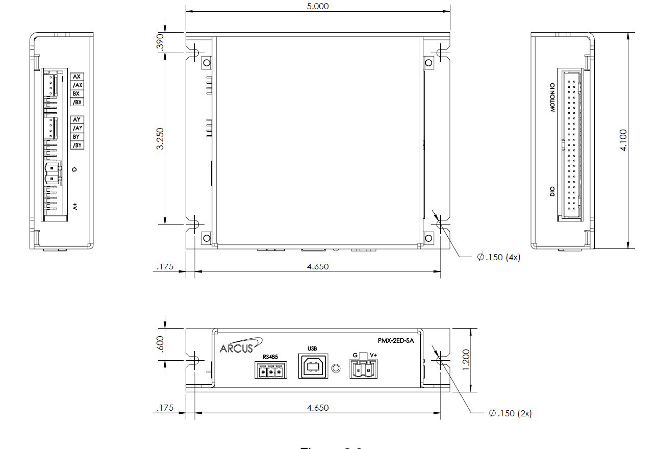
Figure 1: Enclosure dimensions in inches. The drawing is from the PMX-2ED-SA manual and applies to both products.
Front and side panel connectors
The controller power, USB and RS-485 connectors on the front panel, and the motor and driver power connectors on the side panel, have the same pinout, pin order and position on both products. The same mating plugs fit.
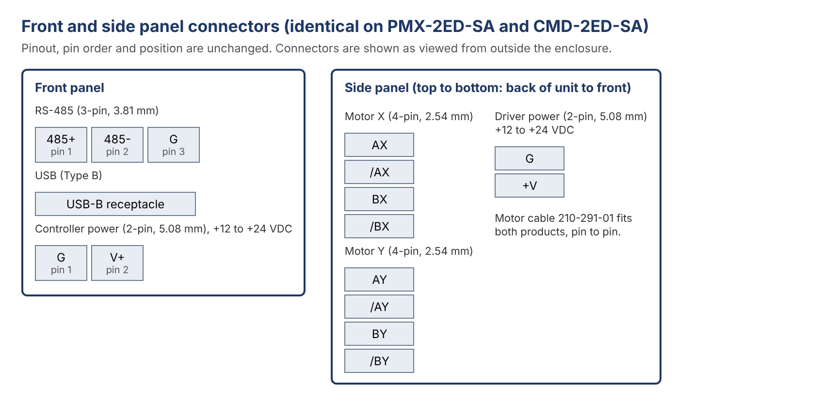
Figure 2: Front and side panel connector pinouts, identical on both products.
Power input
Both products use separate controller (logic) and driver (motor) power inputs, each on the same connector and with the same polarity as before.
|
Specification |
PMX-2ED-SA |
CMD-2ED-SA |
|
Controller power voltage |
+12 to +24 VDC |
+12 to +24 VDC |
|
Controller power current |
0.5 A max |
300 mA |
|
Driver power voltage |
+12 to +24 VDC |
+12 to +24 VDC |
|
Driver power current |
1.5 A max |
2.5 A per motor |
|
Opto supply (50-pin, pin 31) |
+12 to +24 VDC |
+12 to +24 VDC, 250 mA |
|
Reverse-polarity protection |
None |
Added on both power inputs |
|
Note: The CMD-2ED-SA driver can deliver up to 2.3 A per motor, compared with 1.5 A on the PMX-2ED-SA. If you use the higher current settings, make sure the driver power supply can provide up to 2.5 A per motor. |
Communication
USB
The USB Type B connector and its position are unchanged. The host software and drivers are different; see Software Differences.
RS-485
The RS-485 connector pinout (485+, 485-, G) and the supported baud rates (9600, 19200, 38400, 57600 and 115200 bps) are unchanged.
The CMD-2ED-SA has an AC termination (120 Ω in series with 1 nF) permanently fitted across 485+ and 485-. The PMX-2ED-SA had no on-board termination.
|
Note: On a multi-drop RS-485 network, every CMD-2ED-SA on the bus adds this termination load. Take this into account when planning long networks or networks with many units, and when deciding whether to fit external termination. |
50-pin Control/Encoder I/O connector
The 50-pin connector is the same part, in the same position, with the same keying and the same mating connector. Pins 1 to 19, 21 to 23 and 25 to 50 are unchanged. Pins 20 and 24, which were No Connection on the PMX-2ED-SA, are now the X and Y latch inputs.
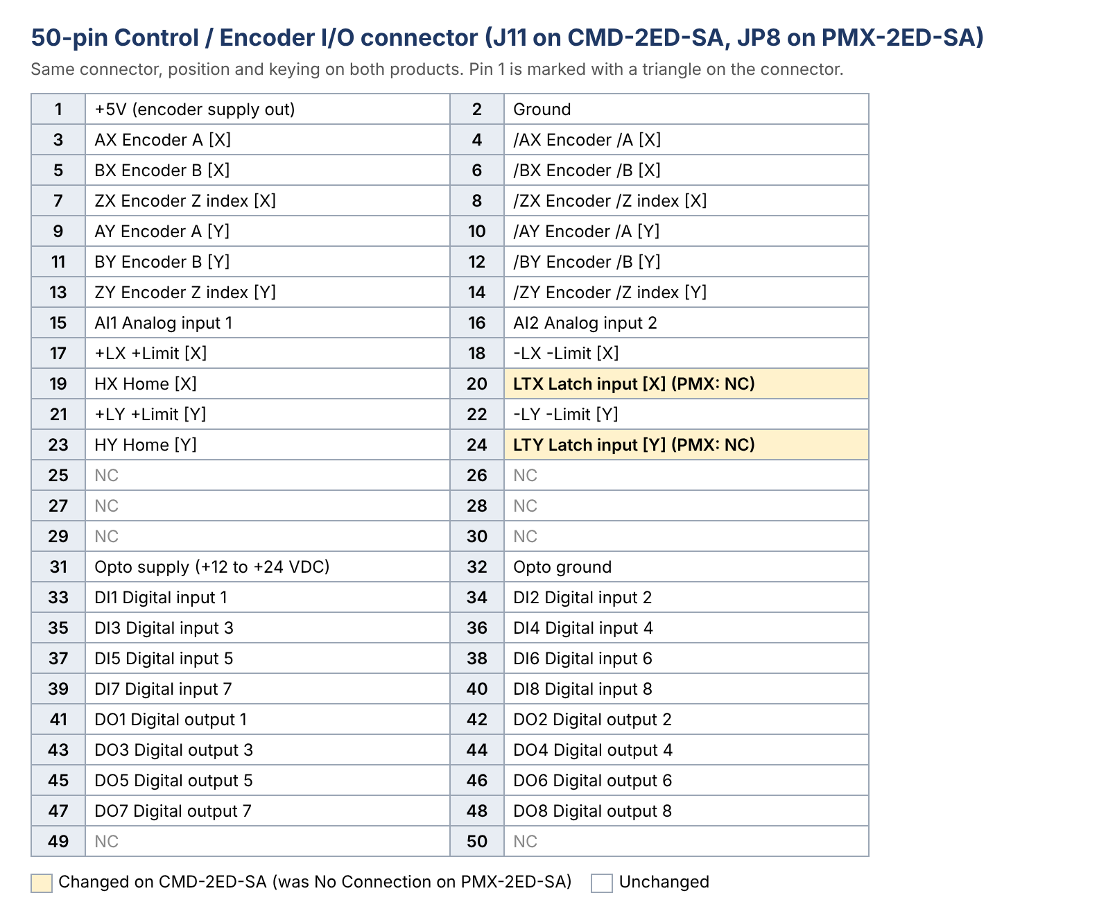
Figure 3: 50-pin Control/Encoder I/O connector pinout. Changed pins are shaded.
|
Note: If your existing cable has wires connected to pin 20 or pin 24, disconnect them or confirm they will not activate the latch inputs. |
Digital inputs and outputs
Digital inputs
There are still 8 opto-isolated digital inputs (DI1 to DI8) on pins 33 to 40, wired the same way: pull the input to opto ground to activate it. The internal series resistor changes from 3.3 kΩ to 3.0 kΩ, so the input current is about the same and no external resistor is needed. The CMD-2ED-SA inputs are specified at 4 to 8 mA and are internally current limited.
Digital outputs
There are still 8 opto-isolated open-collector outputs (DO1 to DO8) on pins 41 to 48, sinking to opto ground (pin 32). The output current rating is lower.
|
Specification |
PMX-2ED-SA |
CMD-2ED-SA |
|
Output type |
Opto-isolated, open collector, sinking |
Opto-isolated, open collector, sinking |
|
Maximum sink current per output |
90 mA |
25 mA |
|
Internal current limit |
None |
None |
|
Collector voltage |
Up to +24 V |
+12 to +24 V (from opto supply) |
|
Caution: Each digital output is rated for 25 mA maximum and has no internal current limit. If any PMX-2ED-SA output drives a relay coil, lamp or other load that draws more than 25 mA, add an external interposing relay or driver before connecting it to the CMD-2ED-SA. |
Motion, latch and analog inputs
The limit and home inputs (+LX, -LX, HX, +LY, -LY, HY) are on the same pins with the same opto-isolated sinking circuit. As with the digital inputs, the internal series resistor changes from 3.3 kΩ to 3.0 kΩ with no change in wiring.
The new latch inputs on pins 20 (X) and 24 (Y) are opto-isolated inputs that capture the axis position. They are used with the Commander latch commands.
The two analog inputs (AI1 and AI2) stay on pins 15 and 16 with a 0 to 5 V input range. Resolution increases from 10-bit to 12-bit. The analog inputs can still be used for joystick control of the X and Y axes.
Encoder inputs
The encoder inputs are fully compatible. The pinout is unchanged, the inputs are TTL compatible, and the maximum input frequency is 5 MHz on both products. The +5 V encoder supply on pin 1 is rated 200 mA on both products.
Motor connection
The motor connectors are fully compatible. The motor cable 210-291-01 used with the PMX-2ED-SA plugs into the CMD-2ED-SA the same way, and the motor phase pins are pin-to-pin compatible. A motor turns in the same direction for the same command.
The built-in driver changes from the Allegro A3977 to the Toshiba TB67S128FTG. This raises the maximum motor current to 2.3 A and adds software-selectable microstepping up to 1/128. The motor voltage range (+12 to +24 VDC) is unchanged.
Driver current and microstep settings
The driver current and microstep settings are set with jumpers inside the unit, as on the PMX-2ED-SA. Remove the cover to change them. The current values are different, and the jumper headers are new: they use 1.27 mm (0.05 in) pitch jumpers, so the 2.54 mm jumpers from a PMX-2ED-SA do not fit.
For the full setting procedure, see Stepper Motor Driver Overview in the CMD-2ED-SA manual.
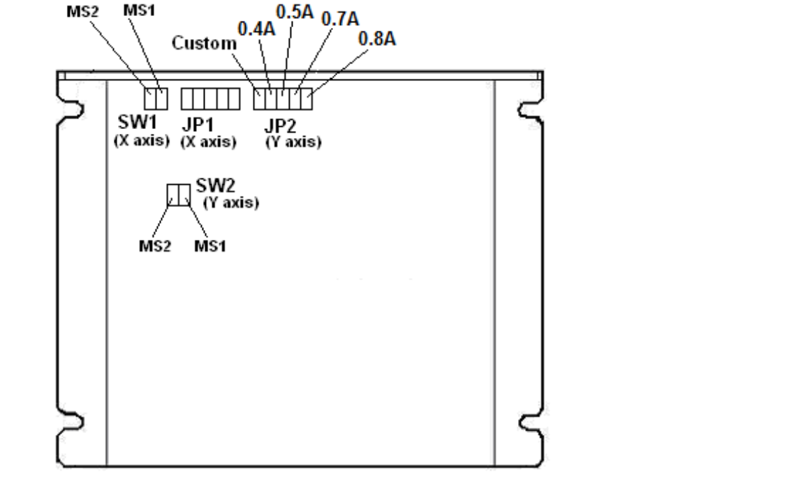
Figure 4: PMX-2ED-SA jumper locations (from the PMX-2ED-SA manual).
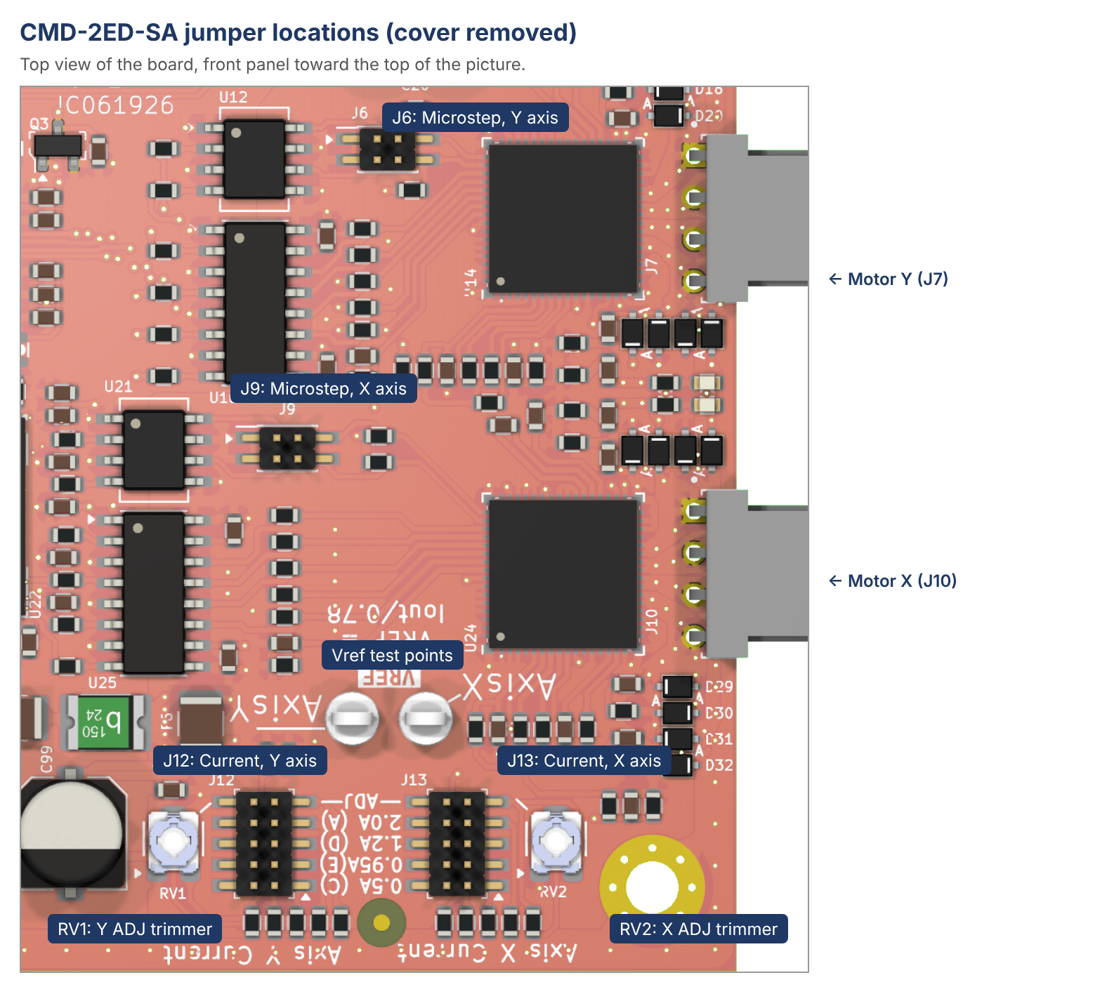
Figure 5: CMD-2ED-SA jumper locations. J13 and J12 set the current; J9 and J6 set the microstep.
Driver current
|
Item |
PMX-2ED-SA |
CMD-2ED-SA |
|
Maximum current |
1.5 A |
2.3 A |
|
Current jumpers |
JP1 (X), JP2 (Y) |
J13 (X), J12 (Y) |
|
Preset values |
0.4, 0.5, 0.7, 0.8 A |
0.5, 0.95, 1.2, 2.0 A |
|
Custom value |
Solder a resistor across the Custom pins |
Fit the ADJ jumper and turn the trimmer (RV2 for X, RV1 for Y) |
|
No jumper fitted |
0 A (motor not powered) |
Maximum current, about 2.3 A |
Use this table to choose the CMD-2ED-SA setting that matches your PMX-2ED-SA setting:
|
PMX-2ED-SA setting |
CMD-2ED-SA setting |
Vref to set with ADJ |
|
0.4 A |
ADJ jumper + trimmer |
0.51 V |
|
0.5 A |
0.5 A jumper (pins 1-2) |
(preset) |
|
0.7 A |
ADJ jumper + trimmer |
0.90 V |
|
0.8 A |
ADJ jumper + trimmer |
1.03 V |
|
Custom resistor |
ADJ jumper + trimmer |
Vref = I ÷ 0.78 |
|
(not available) |
0.95 A, 1.2 A or 2.0 A jumper |
(preset) |
To use ADJ, fit the jumper on the ADJ position (pins 9-10), then measure the voltage at the axis Vref test point against the GND test point (TP1, near the driver power connector) and turn the trimmer until Vref = required current ÷ 0.78.
|
Caution: With no current jumper fitted, the CMD-2ED-SA drives the motor at its maximum current (about 2.3 A), not 0 A as on the PMX-2ED-SA. Always fit a current jumper that suits your motor before applying driver power. Factory default jumper settings: to be added. |
Microstep
The microstep jumper table for full step to 1/8 step is the same as on the PMX-2ED-SA. On the CMD-2ED-SA, MS1 is the jumper position nearer the back of the unit and MS2 is nearer the front panel.
|
Microstep |
PMX-2ED-SA MS1 / MS2 (SW1 X, SW2 Y) |
CMD-2ED-SA MS1 / MS2 (J9 X, J6 Y) |
|
1/8 |
Open / Open |
Open / Open |
|
1/4 |
Open / Closed |
Open / Closed |
|
1/2 |
Closed / Open |
Closed / Open |
|
Full step |
Closed / Closed |
Closed / Closed (not recommended) |
|
1/16 to 1/128 |
Not available |
Set in software with the MSR command; remove all microstep jumpers |
Grounding
On the CMD-2ED-SA, logic ground is connected through a ferrite bead to the four mounting holes and to the USB connector shield. When the unit is screwed to an earthed panel, logic ground is therefore connected to earth through the ferrite. The PMX-2ED-SA did not have this connection.
|
Note: If your system keeps logic ground isolated from the mounting panel, or connects several units and a PC to earth at different points, check the installation for ground loops. |
Indicators
The front panel status LED is unchanged. Inside the unit, the CMD-2ED-SA adds a green Enable LED and a red Motor Power LED for each axis.
Electrical specifications comparison
|
Specification |
PMX-2ED-SA |
CMD-2ED-SA |
|
Controller power |
+12 to +24 VDC, 0.5 A max |
+12 to +24 VDC, 300 mA |
|
Driver power |
+12 to +24 VDC, 1.5 A max |
+12 to +24 VDC, 2.5 A per motor |
|
Opto supply |
+12 to +24 VDC |
+12 to +24 VDC, 250 mA |
|
Reverse-polarity protection |
No |
Yes |
|
Motor driver |
Allegro A3977 |
Toshiba TB67S128FTG |
|
Motor current |
Up to 1.5 A |
Up to 2.3 A |
|
Microstep |
Full to 1/8 (jumpers) |
Full to 1/8 (jumpers), up to 1/128 (software) |
|
Maximum pulse rate (built-in driver) |
400 kpps |
1.28 Mpps |
|
Encoder inputs |
TTL compatible, 5 MHz max |
TTL compatible, 5 MHz max |
|
Digital inputs |
8, opto-isolated, 3.3 kΩ internal resistor |
8, opto-isolated, 3.0 kΩ internal resistor, 4 to 8 mA |
|
Digital outputs |
8, open collector, 90 mA max |
8, open collector, 25 mA max |
|
Limit and home inputs |
6, opto-isolated |
6, opto-isolated |
|
Latch inputs |
None |
2 (pins 20 and 24) |
|
Analog inputs |
2, 10-bit, 0 to 5 V |
2, 12-bit, 0 to 5 V |
|
RS-485 termination |
None |
120 Ω + 1 nF AC, always fitted |
|
Operating temperature |
-20 to +80 °C |
-20 to +80 °C |
|
Storage temperature |
-55 to +150 °C |
-55 to +150 °C |
Last updated Friday, October 16, 2026