
4.0 Stepper Motor Driver Overview
Stepper Motor Driver Overview
The CMD-2ED-SA has two built-in microstep drivers, allowing the controller to directly drive 2 stepper motors.
On this page:
Microstep
The CMD-2ED-SA has 7 microstepping options including half, quarter, 1/8, 1/16, 1/32, 1/64, and 1/128 step . In general, the number of microsteps per revolution can be determined by the follow equation, where "DEGREE" is the full step angle of motor and "USTEP" is the microstep setting.
Micosteps/Revolution = 360° / (DEGREE * USTEP)
For example, using a 1.8° motor and a microstep setting of 1/8, the number of microsteps/revolution would be [360° / (1.8° * 1/8)] = 1600.
Driver Current
The CMD-2ED-SA will have a maximum rated current output of 2.3A. The current settings should not exceed the rated current of the motor being used. Setting the driver current higher than the maximum rated current will overheat and potentially damage the motor. It is recommended to use a current setting that is in the range of 60-80% of the maximum rated current for the motor.
Configuring the Driver Current and Microstep
The CMD-2ED-SA contains a series of jumpers that are used to configure the microstep and driver current settings.
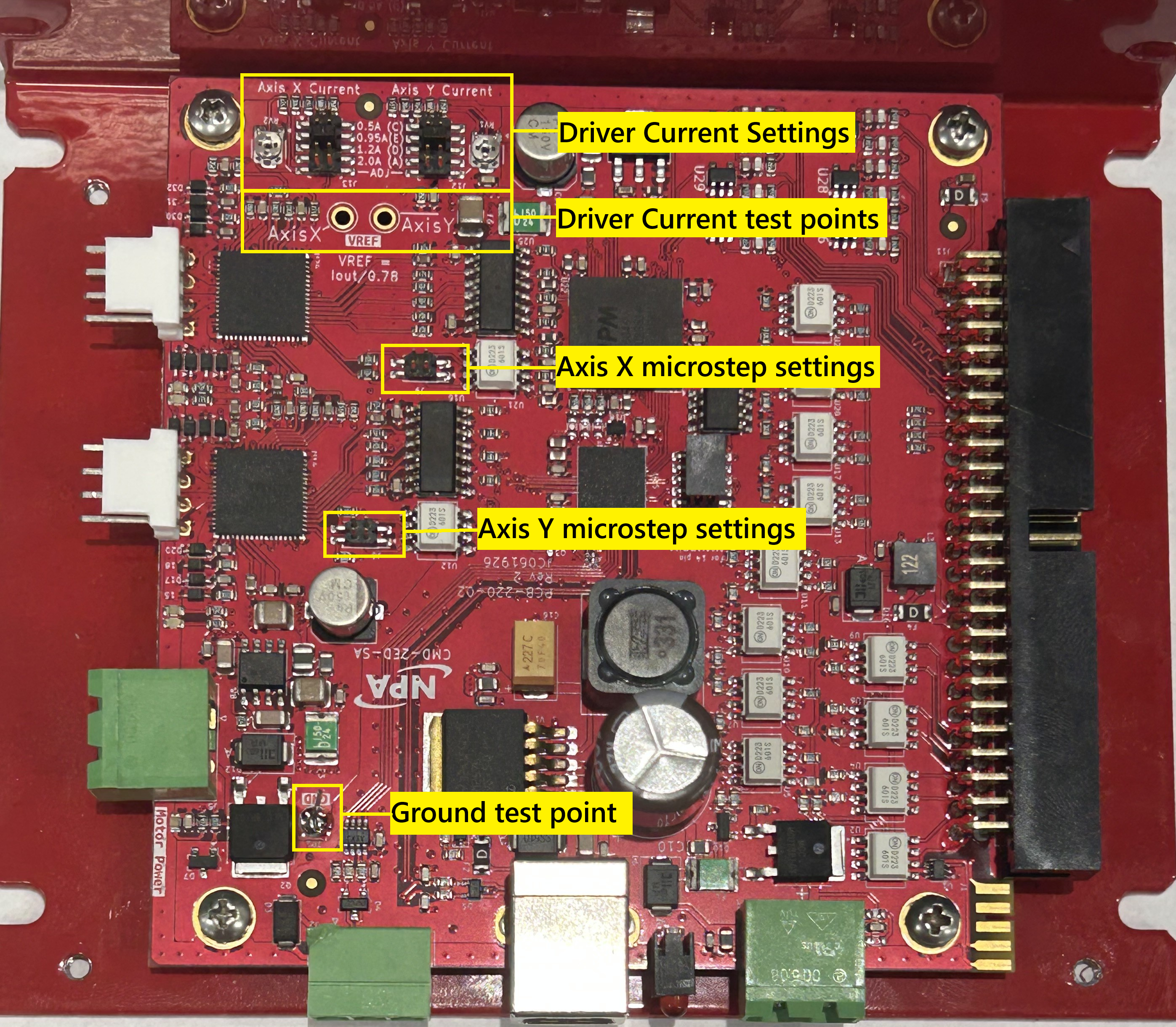
Driver Current
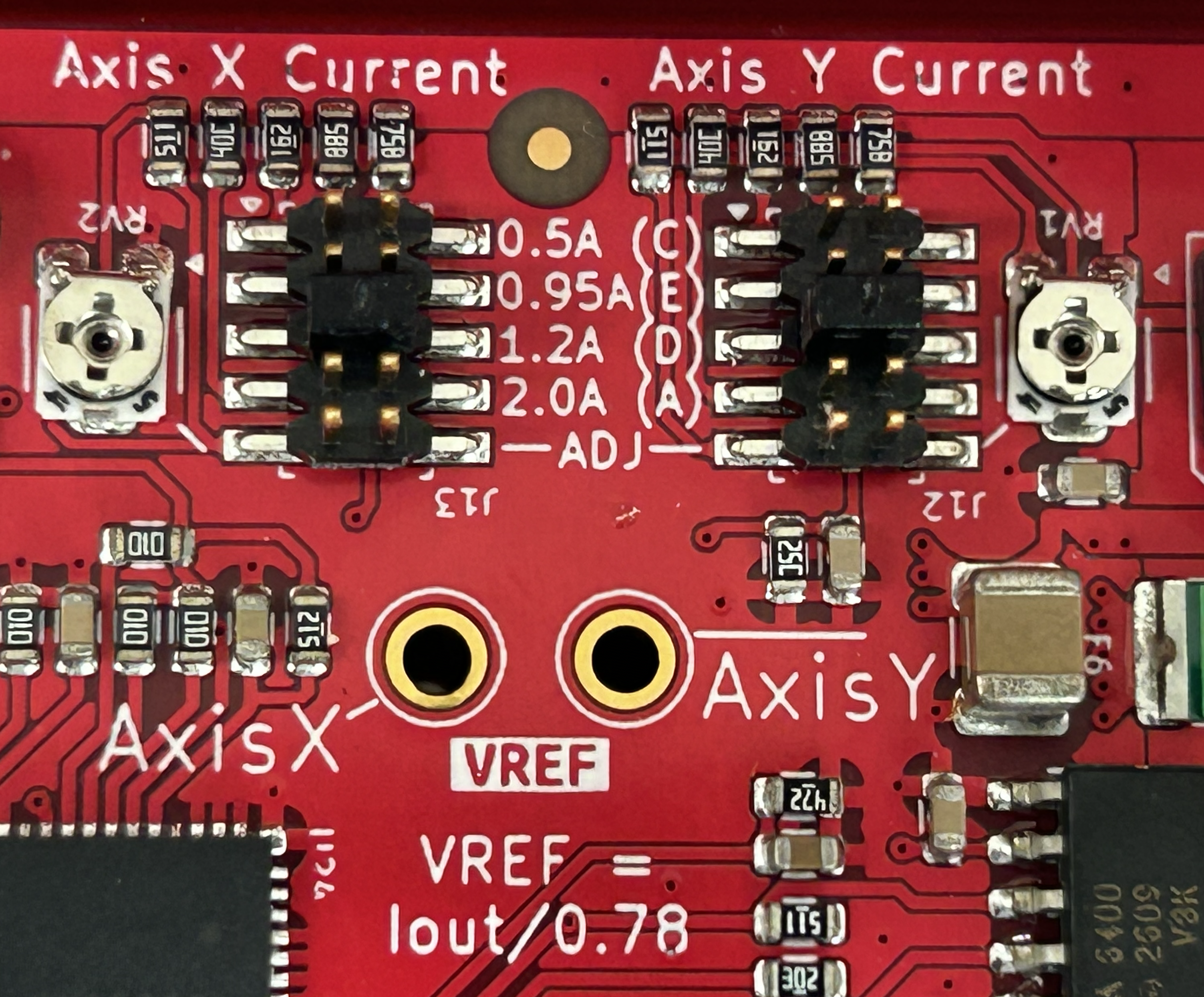 To set the current, open up the top cover. There are two dual row jumper headers J13 (for X axis) and J12 (for Y axis).
For NPA stepping motors
There are four preset current settings to match standard motors from NPA: 0.5A, 0.95A, 1.2A, and 2.0A. Any of these current setting can be selected using the included jumper.
For other stepping motors
For other custom current setting, move the included jumper to the ADJ pins.
- Use the formula below to get the Vref value for the required motor current. The result should be a positive value between 0 and 2.95. For example, to set the current to 0.4A, Vref value would be 0.51V, while for 0.7A, Vref value would be 0.9V.
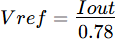
- Using a volt meter, place the positive lead on the test point of the Axis (near current setting jumpers) to be adjusted, and the common lead to the ground test point (near the motor power input).
- Adjust the current setting potentiometer RV2 (for X axis) and RV1 (for Y axis), until the voltmeter shows the value calculated in step 1.
Microstep
The driver microstep settings can be changes in one of two methods. Method 1 hardware, Method 2 software. Method 1 is available to support backwards compability with the PMX-2ED-SA, and only supports full, half, quarter, and 1/8 microstep modes. Method 2 supports all microstep modes and can be changes on-the-fly.
Method 1 hardware setting of microstepping settings.
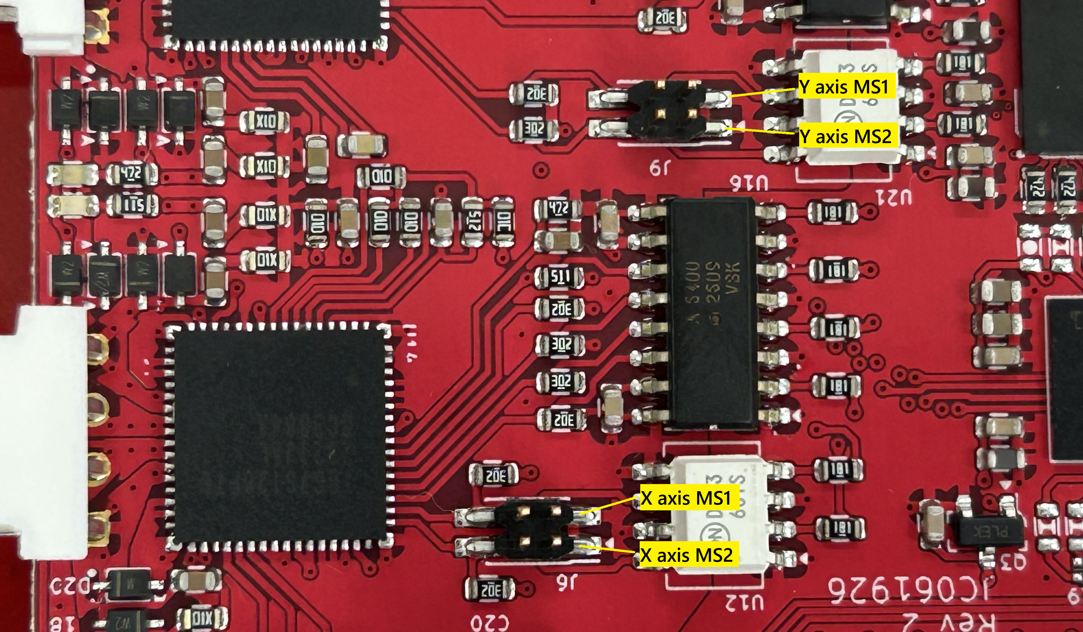 To set the microstep setting, use the J9 (for X axis) and J6 (for Y axis) headers. MS1 is the two pins closer to the back, and MS2 is the two pins closer to the front of CMD-2ED-SA. Full step mode is not recommended
|
microstep |
MS1 |
MS2 |
|
1/8 |
Open |
Open |
|
¼ (quarter) |
Open |
Close |
|
½ (half) |
Close |
Open |
|
Full step |
Close |
Close |
Method 2 software setting of microstepping settings.
To use software setting ensure that J9 (for X axis) and J6 (for Y axis) headers do not have any jumpers installed. Use the MSR[axis] command to set the microstepping resolution that is needed for each axis. If you are using the CMD-2CR firmware then set IO27 to IO29 to set the X axis and IO30 to IO32 to set the Y axis.
|
microstep |
MSR[axis] |
|
1/128 |
7 |
|
1/64 |
6 |
|
1/32 |
5 |
|
1/16 |
4 |
|
1/8 |
3 |
|
¼ |
2 |
|
½ |
1 |