Stepping motors
Precision isn’t just about where a motor ends up—it’s about how it gets there and how firmly it stays there. Whether it’s the silent, micron-level movements of a 3D printer building a medical implant or the relentless torque of a CNC machine carving aerospace components, stepping motors are the unsung heroes of motion control. But not all steppers are created equal. Some thrive in cost-sensitive applications where simplicity reigns, while others push the boundaries of resolution and torque to meet the demands of high-precision robotics. In this chapter, we’ll dissect the two titans of stepping motor technology—Permanent Magnet (PM) and Hybrid (HB)—revealing how their unique structures, winding methods, and drive techniques shape their performance. You’ll discover why a PM motor might be the perfect fit for your air conditioner’s louvers, while an HB motor could be the backbone of your next CNC project. And we’ll uncover the trade-offs behind every design choice, from unipolar vs. bipolar drives to constant voltage vs. constant current control. By the end, you’ll know exactly how to harness the full potential of stepping motors—and when to push beyond their limits.
Structure and Mechanism or Motion: Stepping Motors
Topics:
- Structure of PM (Permanent Magnet) type stepping motors
- Simple and basic drive method: Constant Voltage Drive
- Structure of HB (Hybrid) type stepping motors
- Positions of the stator and rotor teeth of HB type stepping motors
- Coil winding method
- Drive methods (Unipolar and Bipolar)
- How to apply current to the windings of a motor
- Differences in characteristics depending on the drive method
- Excitation methods
- Torque characteristics of stepping motors
- Out-of-step and Hunting can hinder stable motor operations
The two primary types of stepping motors are Permanent Magnet (PM) often called can stack, and Hybrid (HB) stepper motors. PM stepping motors use a rotor with embedded permanent magnets and offer simple control with a power-off detent. Hybrid motors utilize a toothed rotor with an axially magnetized permanent magnet, to maximize power, resolution, and torque in a compact size. HB stepper motors are generally the preferred choice for applications requiring high precision, such as CNC machines, 3D printers, and robotics, due to their superior step resolution and torque characteristics. PM motors provide a balance of cost and performance for less demanding tasks. Let’s explore the design of typical PM and HB stepping motors, focusing on their common and unique features.
Structure of PM (Permanent Magnet) type stepping motors
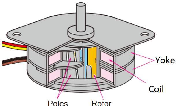
PM stepping motors consist of a rotor, magnetized in the axial direction, and coils within the yoke. They incorporate magnets that enable them to rotate. We will explain the structure based on Figure 1.
|
Figure 1 : Overall view of structure |
Figure 2 : Rotor (Example of 24 poles and 24 magnetizations) |
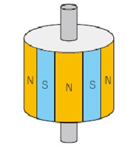
PM stepping motors’ rotating part (rotor) alternately magnetize with north (N) and south (S) poles vertically as seen in Figure 2. A 15° step angle motor combines a total of 24 N and S poles.
The fixed part of PM stepping motors (stators) has parts called poles around which coils are wound, and when current flows through the coil, the poles become electro-magnets. By changing the direction of the current flowing through the coil, the rotor’s magnets attract or repel each other, causing the rotor to move. A motor with a step angle of 15° has 24 poles.
PM type stepping motors rotate gradually as the rotor’s magnets and the stator’s poles attract and repel each other. One rotation is 360°. With 24 rotor magnets and 24 stator poles, 360° ÷ 24 = 15°, meaning the rotor is designed to rotate 15° per electrical signal (one step).
|
Photo 1 : Apperance |
Photo 2 : Disassembled part |
Photo 3 : Enlarged view of the coil part |
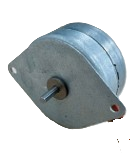
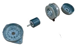
Photo 3 is an enlargement of the coil part. The coil is wound around a donut-shaped bobbin, and when current flows through this coil, the claw-shaped poles inside become electro-magnets. There are two sets of these, and by changing the direction of the current flowing through each coil in a predetermined sequence, the upper and lower poles change to N or S accordingly. The change in the magnetic poles causes the rotor’s magnets to be attracted and repelled, resulting in rotation. By speeding up or slowing down the current flow sequence, the rotor rotates faster or slower.
Simple and basic drive method: Constant Voltage Drive
Constant Voltage Drive is the usual method for driving PM stepping motors, applying a fixed voltage to coils for current. This method has the advantage of a relatively simple circuit configuration, making it easy to reduce costs.
|
CW Rotation |
A-phase (#1-Phase) |
/A-phase (#3-Phase) |
B-phase (#2-Phase) |
/B-phase (#4-Phase) |
CCW Rotation |
|
1 |
ON |
OFF |
ON |
OFF |
4 |
|
2 |
OFF |
ON |
ON |
OFF |
3 |
|
3 |
OFF |
ON |
OFF |
ON |
2 |
|
4 |
ON |
OFF |
OFF |
ON |
1 |
Table 1 : Transistor ON/OFF sequence during 2-phase excitation
In a stepping motor with constant voltage drive, transistors sequentially turn the current to the coils ON/OFF, switching the magnetic poles. This causes the rotor’s permanent magnets to be attracted or repelled by the magnetic poles, resulting in precise step rotation. The 2-phase excitation method especially achieves high torque and stable rotation through constant excitation of two coils (Figure 3, Table 1).
|
Drive transistors and coil |
|
How the rotor rotates |
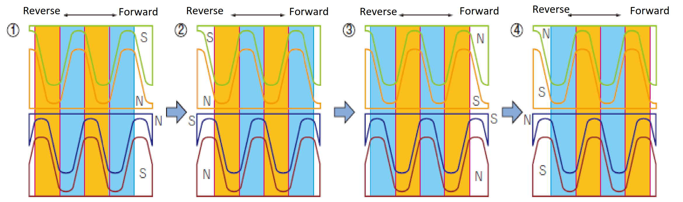
Figure 3 : Rotor rotation by Constant Voltage Drive
Structure of HB (Hybrid) type stepping motors
A Hybrid type stepping motor shown in Photos 4-6 operates by fixed magnetic field created by the permanent magnet inside the rotor and the changing magnetic field by the current flowing through the stator’s coil, with each fine tooth attracting or repelling each other to rotate in precise steps.
|
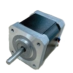
Photo 4 : HB Type Stepping Motor Overall |
Photo 5 : Internal structure |
Photo 6 : Rotor |
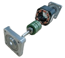
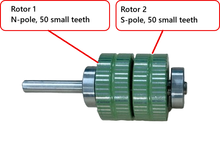
A rotor (rotating part) is characterized by the permanent magnet embedded in its center (Figure 4-6). This permanent magnet is arranged to penetrate the rotor, and at both ends, parts called rotor cores with convex small teeth are attached.
|
Figure 4 |
Figure 5 |
Figure 6 |
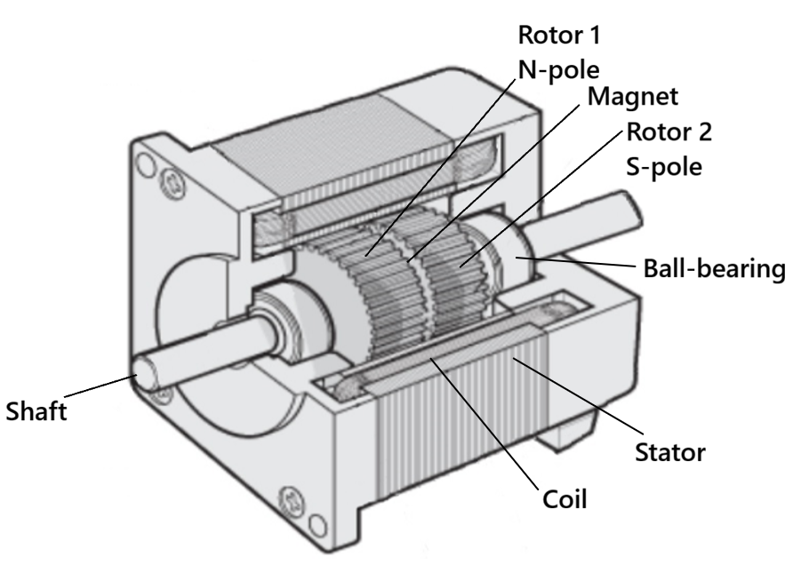
Inside the motor, a stator (fixed part) is arranged to surround the rotor, and there are poles (protrusions with teeth) around which coils are wound. These poles also have convex small teeth like the rotor.
Positions of the stator and rotor teeth of HB type stepping motors
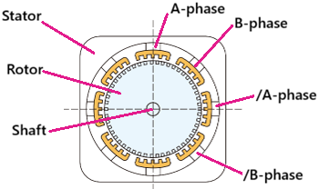
Let’s look deeper into the about 2-phase HB stepping motors. The figure below illustrates how the poles of the stator’s and rotor’s small teeth are positioned relative to each other. To make it easier to understand, we will explain it on a flat plane instead of using a circular shape.
The stator’s poles are located at 45° intervals, totaling eight. Each pole has coils wound around it so that it becomes an electromagnet when current flows. The direction of the current flow determines whether the small teeth become either N (North) or S (South) poles. Rotor 1 and Rotor 2 each have 50 small teeth per rotation with concave and convenes alternating, and they contain permanent magnets inside.
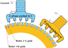
Rotor 1 is the North pole and Rotor 2 is the South pole. The pitch of the peaks of the rotor’s small teeth is 7.2°, and the pitch of the peaks of Rotor 1’s and Rotor 2’s small teeth is 3.6°. The stator’s small teeth and the rotor’s small teeth are offset by 1.8° for each pole as shown in Figure 4 below.
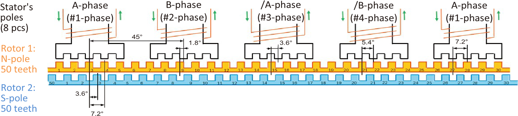
Figure 7 : Teeth of Rotor 1 and Rotor 2 are offset
The winding direction of A- and B-phase coils is opposite to that of /A and /B-phases.
Coil winding method
Regardless of PM type or HB type, there are two types of coil winding methods for stepping motors: unifilar winding and bifilar winding (Figure 8). Unifilar winding is a method of winding with a single wire.
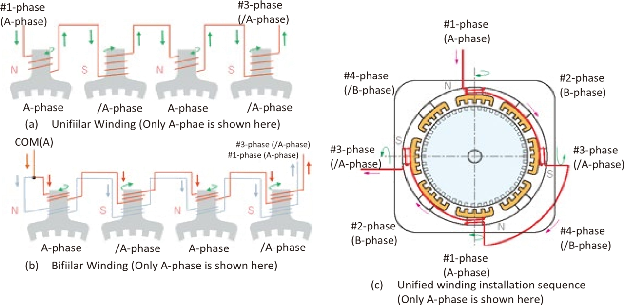
Figure 8 : Coil Winding Method
Drive methods (Unipolar and Bipolar)
Regardless of HB type or PM type, there are two types of drive methods for stepping motors: Unipolar Drive and Bipolar Drive. These drive methods differ in the way the current is applied to the coil, and then how many transistors will be required accordingly.
Unipolar drive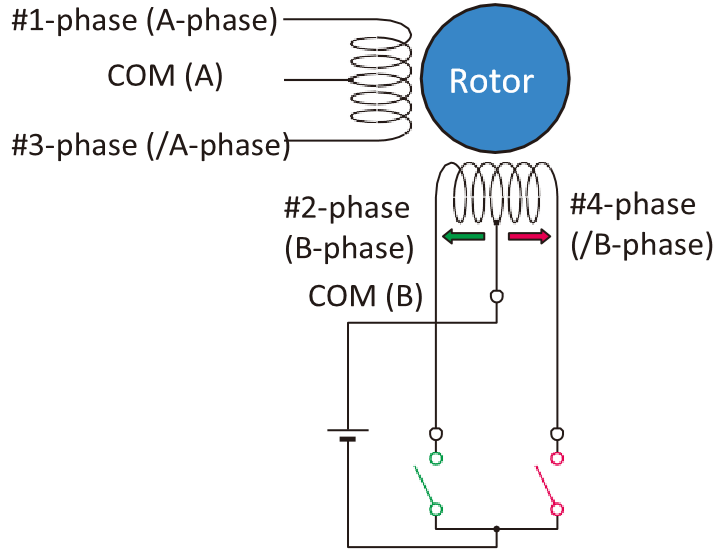
Unipolar drive is a method of driving stepping motors by applying current in only one direction to the coil. The bifilar winding method uses two coils on the stator, and the current flows from the common line (COM) to the target coil winding in one direction. Since the direction of the current does not need to switch, the circuit becomes simple.
Each coil winding requires one transistor to control the ON/OFF of the current. Generally, four transistors are used for a 2-phase stepping motor.
The advantages of this Unipolar drive are that the circuit configuration is rather simple, and control is relatively easy. Faster current direction changes are possible since there’s no reverse current to overcome with each switch, enabling 40% higher speeds when compared to a Bipolar drive. While the disadvantage is that only half of the coil is used, resulting in smaller torque generation (especially at low speeds). Power consumption is also inefficient.
Bipolar drive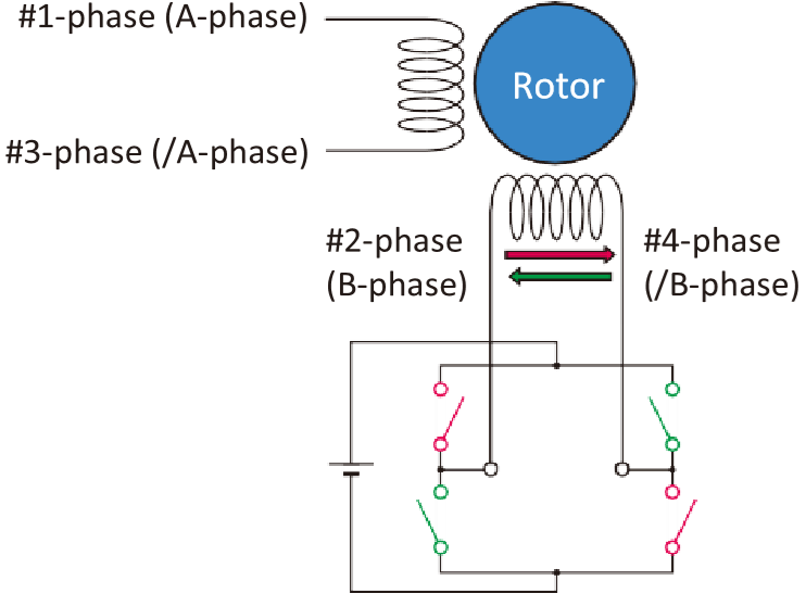
Bipolar drive is a method of driving by alternately applying current from both directions to a unifilar-wound coil. By switching the direction of the current, the magnetic poles of the coil will be reversed.
Using switching elements (transistors) connected to both ends of the coil, the current is reversed while flowing. This allows efficient use of the entire coil.
To perform the bidirectional control of current, a circuit called the “H-bridge circuit” is required. Typically, four transistors are required for one coil, and a total of eight transistors are used for a 2-phase stepping motor.
An advantage of this Bipolar drive is that the entire coil is used, allowing for greater torque generation than a unipolar drive, at low speeds. While the disadvantages include the circuit becoming complex due to the H-bridge circuit, and the cost is higher than unipolar drive due to the large number of transistors used. Plus, the current has to switch direction, which fights against a reverse current with every switch. This reduces the top speed when compared to a unipolar drive.
How to apply current to the windings of a motor
Performance isn’t only about whether the drive is unipolar or bipolar; the current control method matters too. Let us now review the common methods and their advantages and disadvantages.
Constant Voltage Drive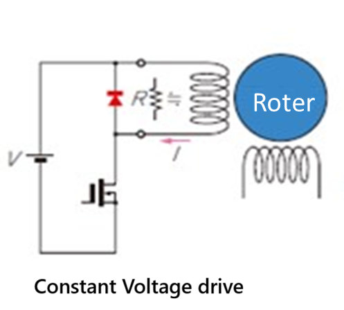
The Constant Voltage Drive is a method of constantly applying a fixed voltage to the motor coils. The coils have resistance (R) and inductance (L) components, so it’s easy to assume that the current is determined by voltage ÷ resistance (I = V/R). However, the motor coils have high inductance, so the current does not immediately reach its maximum value even when voltage is applied. It has a characteristic that the current rises slowly.
Since it only requires a circuit to maintain constant voltage, the configuration is relatively simple, allowing for cost savings.
The current flow becomes too weak as the motor speeds up. Consequently, torque generation decreases sharply, making it prone to out-of-step (a phenomenon where the motor skips steps). Even at low speeds or when stopped, the rated current constantly flows through the coil, leading to a tendency for increased heat generation. Due to its inferior performance at high speeds, this driving method has not been widely used recently.
Constant Current Drive (Chopper Drive)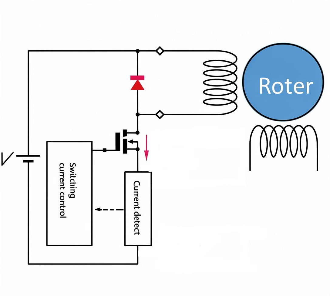
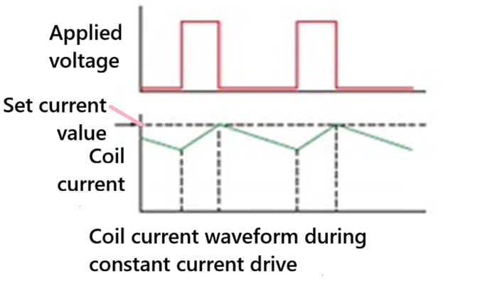
The constant current drive is a method that controls the current flowing through a motor coil to maintain a constant value. To address the issue of current rising difficulty due to coil inductance, the current is controlled by applying a higher voltage and temporarily cutting off the voltage (chopping) when the current is about to exceed the set value.
By counteracting the influence of coil inductance, it allows quick current flow even at high rotating speeds, maintaining stable torque across a wide range of speeds. This makes it less prone to out-ofstep. However, since the circuit is required to monitor the current and rapidly switch the voltage ON/OFF (chopping), it is more complex and costly compared to the constant voltage drive.
Features like current-down function, which reduces the current value as needed, can be utilized to easily suppress heat generation during stops.
Precise control of current values allows for smoother and more accurate positioning when combined with micro-step drive (a drive method that further divides each steps).
In recent applications where high-speed performance and stability are required, this constant current drive method has become the mainstream. Various driver ICs for stepping motors adopt the constant current drive.
Differences in characteristics depend on the drive method.
The characteristics of combinations involving the Unipolar Drive, Bipolar Drive, Constant Voltage Drive, and Constant Current Drive are as shown in Table 2.
|
Winding/ Drive method |
Constant voltage drive |
Constant current drive |
|
Unipolar |
Simple and inexpensive circuit control. Difficult to change torque characteristics. Suitable for applications where easy operation is required, not seeking characteristics |
Complex circuit configuration (it can be improved by using ICs). High responsiveness. Easy to change characteristics by current. The circuit is complex, but it can effectively utilize motor characteristics. The price difference from the constant voltage drive circuit has decreased recently due to IC implementation. |
|
Bipolar |
Low speed. Difficult to change torque characteristics. Despite complex circuits, the characteristic improvement is limited, so it is not commonly used. |
Complex circuit configuration (it can be improved by using ICs). Easy to change characteristics by current. Can improve the motor torque characteristics. The circuit is complex, but it can effectively utilize motor characteristics. The price difference from the constant voltage drive circuit has decreased recently due to IC implementation. |
Table 2 : Differences in characteristics depending on the drive method
Here is a video about these differences.
Excitation methods
1-phase excitation
In this method, only one phase (coil) constantly receives excitation in a 2-phase stepping motor. In this method, the motor operates by a basic step angle. For a basic step angle of 1.8°, it rotates once by 200 steps. Compared to 2-phase excitation, the torque generated by the motor is smaller, and the performance to suppress vibration during rotation (damping characteristics) is also inferior, so it is rarely used. See figure 9 (By Wapcaplet; Teravolt. The original uploader was Teravolt at English Wikipedia.)
Figure 9 : Example of 1-phase excitation
2-phase excitation
This method excites two phases (coils) simultaneously. It is the same excitation method as 1- phase excitation, the motor operates by its basic step angle. For a basic step angle of 1.8°, it rotates once by 200 steps. Since two coils always generate magnetic force, the torque by a motor is larger, compared to the 1-phase excitation, and the rotation is more stable. Therefore, the 2-phase excitation is the most commonly used excitation method.
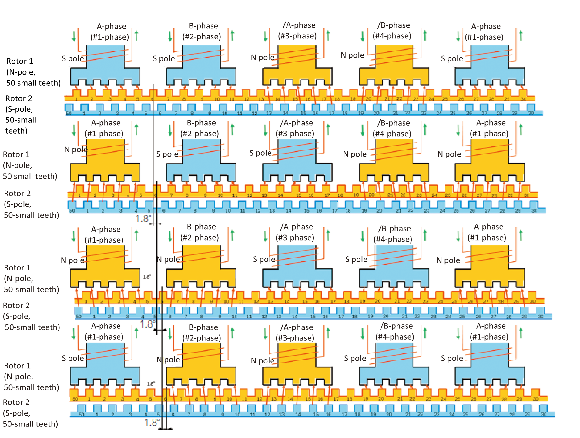
Figure 10 : 2-phase excitation to drive a motor by the basic step
Figure 10 shows a specific example of 2-phase excitation. First, apply current to Aphase and B-phase, setting the stator’s small teeth the S-pole. The rotor’s N-pole small teeth are attracted to these stator’s small teeth in the S-pole. At the same time, current is applied to /A-phase and /B-phase, setting them the N-pole. The S-poles of the rotor are attracted to the N-pole. The rotor stops when the rotor and the stator are balanced.
Next, when B-phase and /A phase of the stator are set in the S-pole, and A-phase and /B-phase are in the N-pole, the rotor rotates 1.8°, which is 1/4 of the small teeth pitch of 7.2°. By changing the way of current flows through the stator sequentially, the rotor rotates by the basic step angle. Figure 10 show these 4 steps in
1-2 phase excitation (Half-Step Drive)
1-2 phase excitation is a method that alternates between 1-phase excitation and 2-phase excitation. For example, 1-phase excitation is performed in the first step, and 2-phase excitation in the next step. This alternating excitation adds intermediate stop positions to the motor, doubling the resolution. In other words, for a basic step angle of 1.8°, it rotates once in 400 steps. This enables smoother rotation and is particularly effective in reducing motor vibration.
Micro-step drive
Micro-step drive is an advanced excitation method to further divide the stopping position of a stepping motor. This is achieved by precisely adjusting the balance (dividing) of current flowing through multiple coils such as A-phase and B-phase(division).
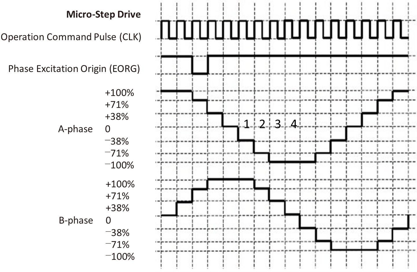
Figure 11 : Micro-Step Drive Waveform
For example, in the case of “Micro-Step of 1/4” for a basic step angle of 1.8°, this 1.8° is divided into four, allowing it to stop at an angle of 1/4 (0.45° in this case). This allows the motor to position very smoothly and accurately. It greatly contributes to reducing vibration and noise, so it is widely used in medical devices, optical equipment, and precision robotic arms where high-precision control is required.
Torque characteristics of stepping motors
The torque characteristics of stepping motors are an essential element for evaluating their performance and selecting them for appropriate applications (Figure 12).
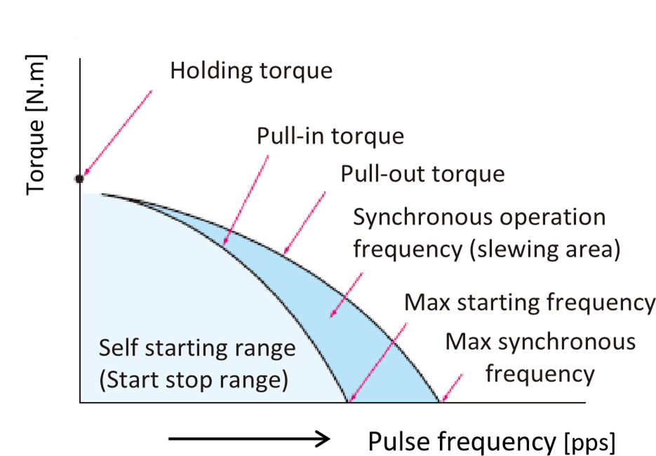
Figure 12 : Torque characteristics of a stepping motor
Holding torque...refer to the stability when stopped
Holding torque refers to the maximum torque that an excited stepping motor can maintain its stopping position against external forces or load fluctuations. This number indicates how stable the motor is when stopped; a higher number means less chance of shaking or losing its position.
Pull-in/Pull-out torque...key to understand the dynamic torque characteristics
Pull-in torque is the highest torque a motor can handle when starting from zero speed and running at a certain frequency without losing synchronization. It indicates the ability to directly start moving heavy loads, especially at low-speeds. On the other hand, pull-out torque is the maximum torque at which the rotor can follow the driving pulse frequency and operate synchronously without miss-stepping. This indicates how much the motor sustains during synchronous operation and is important for evaluating performance at high speeds. Generally, pull-out torque indicates higher than pull-in torque value.
Max self-starting frequency/ Max response frequency...how fast it can follow
Maximum self-starting frequency refers to the highest pulse frequency at which a stepping motor with no-load can start directly without out-of-step states. When exceeding this frequency, the motor cannot start normally. In contrast, maximum response frequency is the highest pulse frequency that a motor, once in synchronous operation, can follow without out-of-step states.
Synchronous operation range...set by torque and frequency characteristics
The synchronous operation range is where the rotor can operate synchronously without out-of-step states when the drive pulse frequency is gradually increased beyond the self-starting range or when the load torque is increased. When controlling at high speed, the motor must start and stop in the self-starting range, so gradually increase the speed from the self-starting frequency range. After operating in the synchronous operation range, it is necessary to control the speed to decrease and stop in the self starting frequency range.
When selecting a motor, it is necessary to choose a motor with specifications that can be controlled within this self-starting frequency range and synchronous operation range.
Out-of-step and Hunting can hinder stable motor operations
Out-of-step
Out-of-step is a phenomenon where the rotor of a stepping motor can no longer follow the changes in the excitation of a stator.
If the load on the shaft is too large, rapid acceleration/deceleration is applied, or the pulse frequency exceeds the motor’s capacity, the excitation switches before the rotor reaches the next step position, resulting in an error from the correct position (Figure 13). If this repeats, the motor will either stop or continue unintended rotations, making accurate positioning impossible.
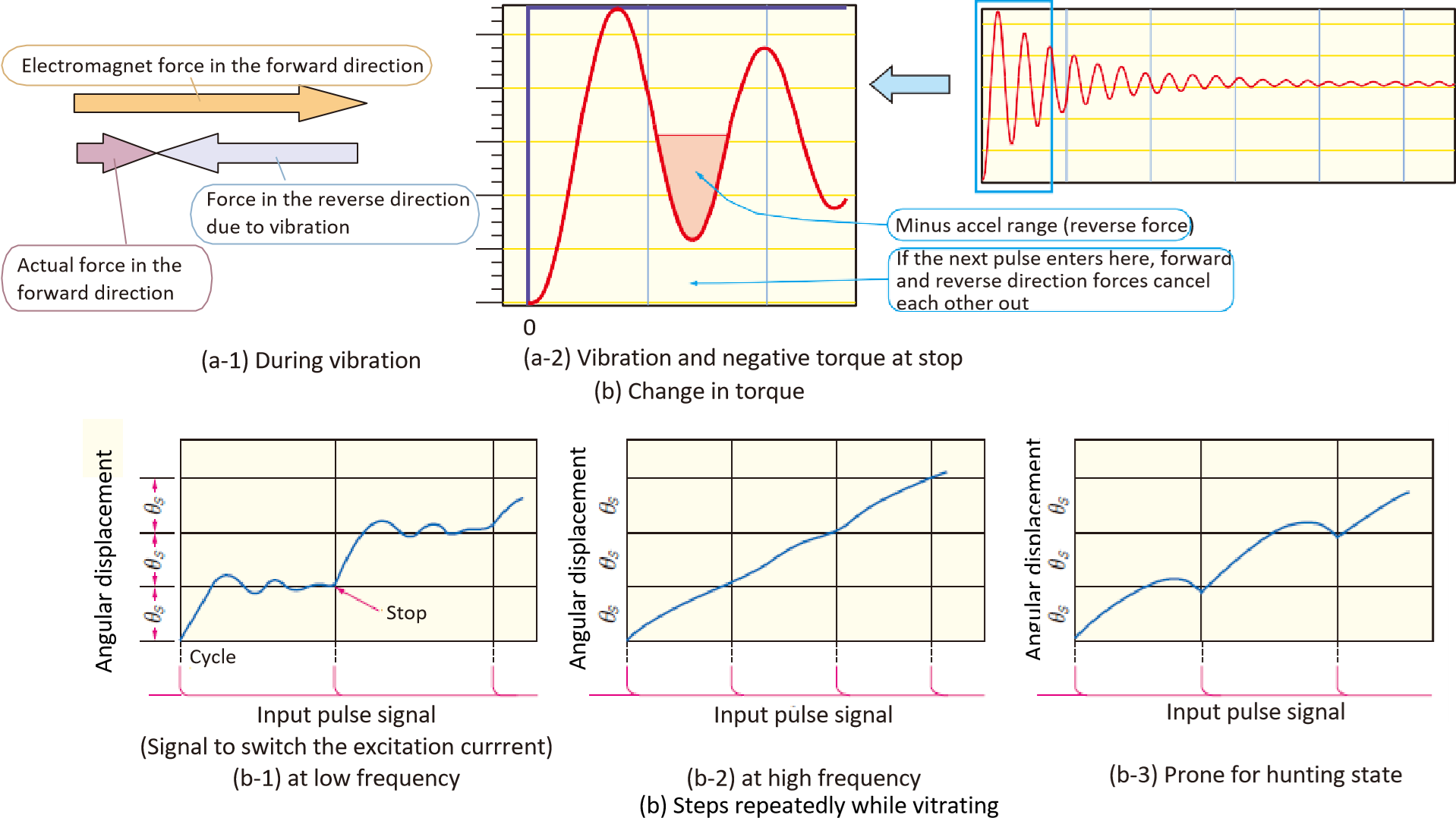
Figure 13 : Out-of-step mechanism
Hunting/ Disturbance in operation
Hunting is different from the Out-of-step state; it is a phenomenon where a motor vibrates during step rotation. When the rotor of a motor aims for a target position, it may generate inherent vibrations (resonance) during this process. If the next pulse is input during this vibration, the forces to rotate the motor and to reverse the motor due to the vibration, may collide and cancel each other out. This causes the rotor to not move smoothly, resulting in temporary position error and operational instability. The following methods are effective as countermeasures for this problem:
|
This section took you deep into the world of stepping motors, from the rugged simplicity of Permanent Magnet (PM) types to the high-resolution precision of Hybrid (HB) designs. We explored how their structures—rotors, stators, and winding methods—dictate their performance, and how drive techniques like unipolar, bipolar, constant voltage, and constant current control shape their torque, speed, and efficiency. You saw how excitation methods, from 1-phase to micro-stepping, can transform a basic stepper into a smooth, high-resolution powerhouse, and how torque characteristics like holding torque, pull-in, and pull-out torque define their real-world capabilities. But we also uncovered their limitations: out-of-step errors, hunting vibrations, and the trade-offs between cost, complexity, and performance. Stepping motors are the workhorses of open-loop positioning, but what happens when your application demands even greater adaptability, speed, or precision? That’s where servo motors come in—and in the next chapter, we’ll explore how they rise to the challenge.
Now that you’ve mastered the art of stepping motors, it’s time to meet their closed-loop counterparts: servo motors. Unlike steppers, which rely on open-loop precision, servos use real-time feedback to dynamically adjust position, speed, and torque—making them ideal for applications where adaptability is non-negotiable. In the next section, we’ll break down the structure of servo motors, from their high-speed rotors to their high-resolution encoders, and compare the three most common control methods: motion control, analog control, and serial-bus control. You’ll learn the basics of PWM (Pulse Width Modulation) and how it enables servo motors to deliver smooth, high-torque performance. Ready to close the loop?