Introduction to motion control
Motion control at its basis is the accurate, repeatable positioning of motors. Precise motor control is the hidden technology that makes modern tools like 3D printers and surgical robots work. However, not all motion control systems perform equally. Some excel at holding a position with ironclad repeatability, while others adapt on the fly to handle unpredictable loads at blistering speeds. In this training module, we’ll explore the workhorses of motion control:
- Key differences in motor types, winding chooses, driver types, control methods, and feedback mechanisms.
- Applications where each motor excels (e.g., open-loop vs. closed-loop systems).
- Control challenges and how dedicated motion control LSIs simplify implementation.
Behind every high-precision motion system is a fundamental choice: stepping motor or servo motor? This isn’t just an engineering decision; it’s a trade-off between simplicity and sophistication, cost, and capability, rigidity, and adaptability. We will uncover why choosing the right one can mean the difference between a system that works and one that excels.
In this introductory section, we will broadly examine motion control, point out where it appears, discuss the most common motor types, explain what is necessary to position a motor accurately, and describe how a motion control LSI works. Later sections will dive deeper into each of these topics.
Introduction: Motion control is actively used in places like these!
Topics:
Everyday Products
Many products that you may interact with every day use stepper or servo motors.
|
Surveillance and monitoring cameras The orientation of surveillance and monitoring cameras needs to be controlled to capture specific areas or targets. Horizontal left-right movement is called “Pan”, and vertical inclination movement is called “Tilt”. Stepping motors accomplish the operation of these mechanisms. The strength of stepping motors is that they rotate by a fixed angle according to the number of input pulse signals. Therefore, the camera’s orientation can achieve high precision even with open-loop control and no position sensors. Additionally, servo motors are actively used in large cameras, such as in weather cameras. |
|
|
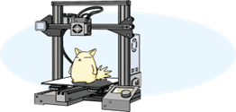
3D Printer Small 3D printers, especially with the popular FDM (Fused Deposition Modeling) method, create objects by stacking thin layers while melting resin filament. In such applications, precise positioning according to the required accuracy of the modeling is essential. Stepping motors and servo motors meet this demand. |
|
|
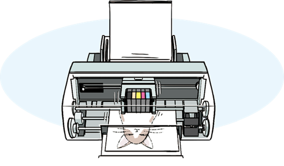
Inkjet Printer Inkjet printers use stepping motors for two key functions that affect print quality: moving the print-head with precision and feeding the paper accurately. Stepping motors are more affordable since they don’t require position encoders or complex feedback loops. That reduces the number of components used in the system, thus lowering manufacturing costs. |
|
|
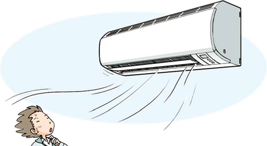
Air Conditioner Stepping motors rotate according to pulse signals, allowing precise control of the louver angle to adjust wind direction. It prevents wind from hitting the body, circulates air throughout the room, or allows pinpoint airflow to specific locations. Air conditioners used in living rooms and bedrooms emphasize quietness. Stepping motors face challenges with vibration and noise caused by the stepping movement; however, with the development of micro-step drive technology, smooth and quiet operation is now possible. |
|
|
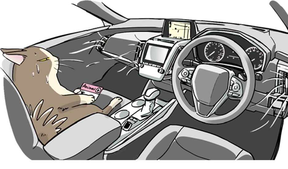
Automobile (Interior) Stepping motors are utilized in meters and air conditioner vents. They are designed to rotate by a fixed angle with pulse commands, allowing them to stop and hold at precise positions without sensor feedback. This makes the motors suitable for precise control of meter needles or air-conditioning louvers. |
|
|
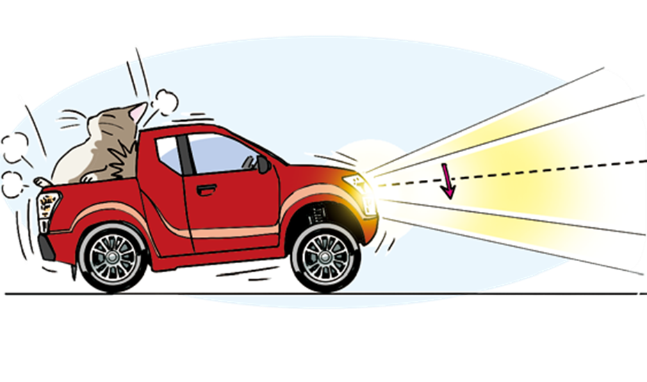
Headlight Alignment Loading heavy luggage in the car trunk or having many passengers in the rear seats can cause the rear of the vehicle to sink, misaligning the headlight axis upwards. An ‘auto-leveler’ function corrects the axis misalignment because this condition can blind oncoming vehicles. Even non-luxury cars can easily adjust the axis with a switch at hand. In such situations, stepping motors adjust the axis up and down by moving the reflector within the light unit based on commands from the control module. |
|

Medical/Analytical Equipment
Medical devices and analytical equipment requires high reproducibility and precision for tasks such as accurately dispensing small amounts of liquid, moving tiny samples to specific positions, or precisely moving optical lenses. Stepping motors can meet these demands at low cost.
|
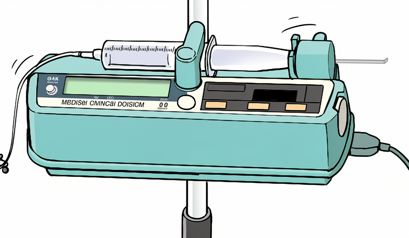
Syringe Pump The expected function of a syringe pump is to dispense accurate amounts of liquid. Stepping motors can rotate according to the number of input pulse signals. By attaching a lead-screw or a ball-screw to the motor’s rotation axis to convert rotational motions into linear motions, the syringe piston can be accurately and stably dispensed. Also, stepping motors with built-in screw mechanisms are available. |
|
|
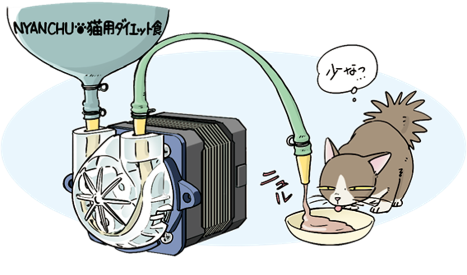
Tube Pump The movement of a tube pump involves squeezing a flexible tube with rollers and pushing the crushed part to dispense liquid. To control the pump’s flow rate, the roller speed must be precisely controlled. Stepping motors are suitable for such applications, as they operate in sync with the pulse train speed in a simple control configuration. Tube pumps have the advantage of dispensing high-viscosity liquids or slurries (mud-like liquids) without clogging due to their structure. Stepping motors output strong torque when starting slowly at low speeds, making it easier to dispense highly viscous liquids. |
|
Industrial Machinery
Many industrial machines often position and transport heavy products or parts at high speed or perform processing which requires large force. Positioning motors are actively used in such situations. Stepping motors tend to lose torque at high speeds, so servo motors, which can output relatively large torque from medium to high speeds, are actively used in applications requiring significant output.
|
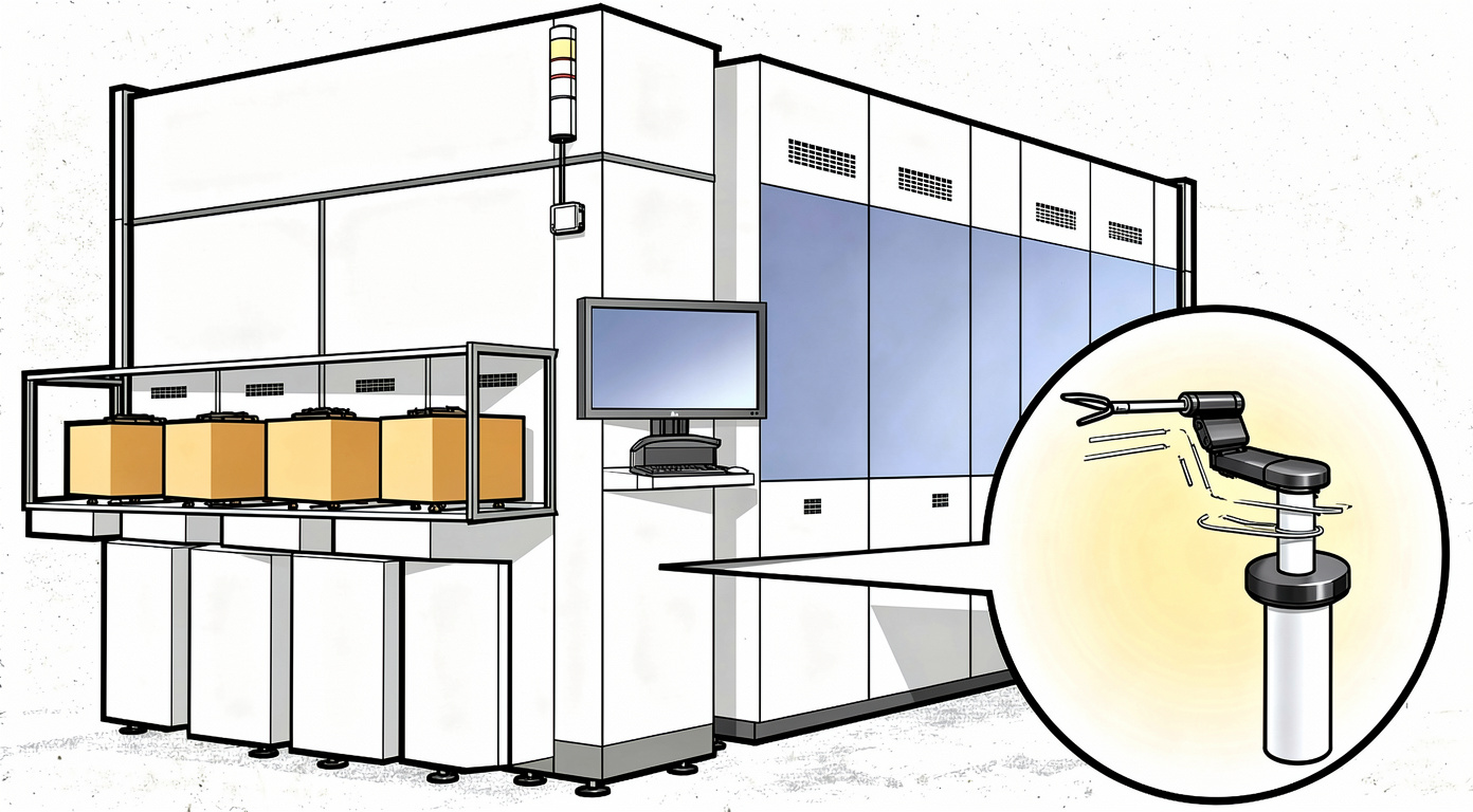
Semiconductor Manufacturing Equipment Wafer acceptance and transport use transporting robots (horizontal multi-joint robots) shown on the right side of the image. Servo motors and stepping motors are utilized in various processes, including direct transport mechanisms, wafer processing, and bonding and packaging of cut elements. |
|
|
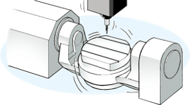
CNC Machine CNC machines have multiple axes, such as X, Y, and Z axes (sometimes four or more axes), and move tools or work pieces according to the desired object shapes. Due to the nature of CNC machining, which involves cutting the object, tools must be moved continuously without stopping to avoid uneven machining results. Providing continuous commands to servo motors is required for continuous machining. |
|
|
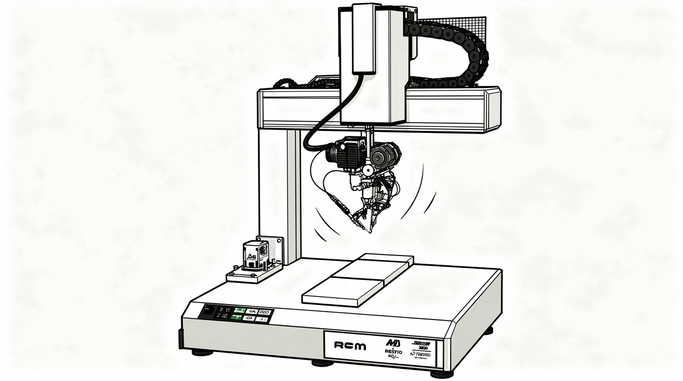
Soldering Equipment The figure shows a soldering robot as an example of an automatic assembly device. Servo motors and stepping motors are used in the drive parts of such devices, such as the X, Y, and Z axes, to ensure accurate movement to the desired position. In automatic assembly devices, servo motors are used when high speed, power, and precision are required, while stepping motors are used for cost effective and precise positioning in small/desktop type devices. |
|
|
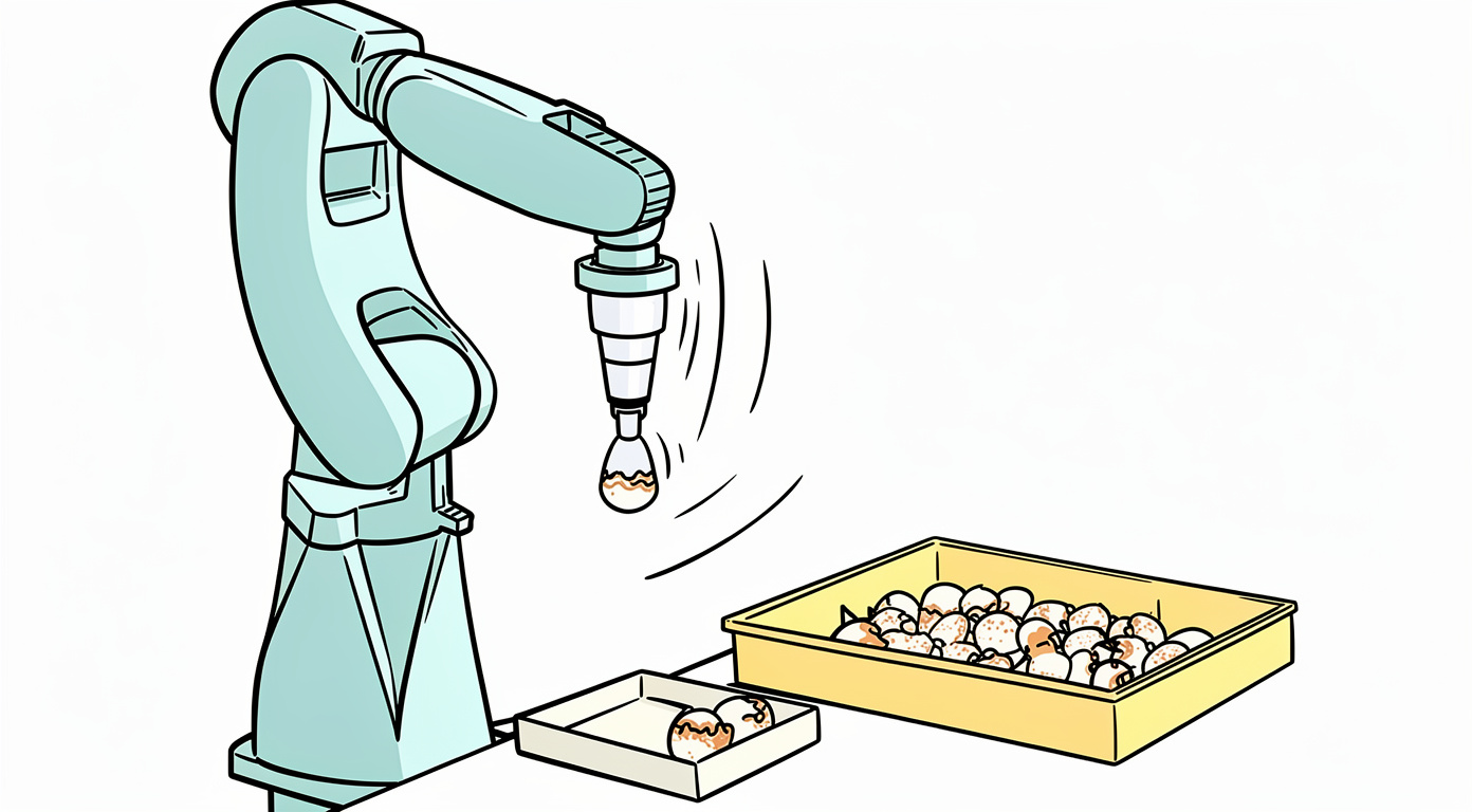
Robot Arm Precise positioning is essential for robot arms to grasp work pieces (target objects) or move tools (welding torches, grippers, etc.) to accurate positions. In robots that exert strong force, servo motors perform closed-loop control to reach the target position accurately. This control can be performed by continuously correcting the error between the target position and the current position based on the feedback from an encoder by closed-loop control. |
|
Motor types
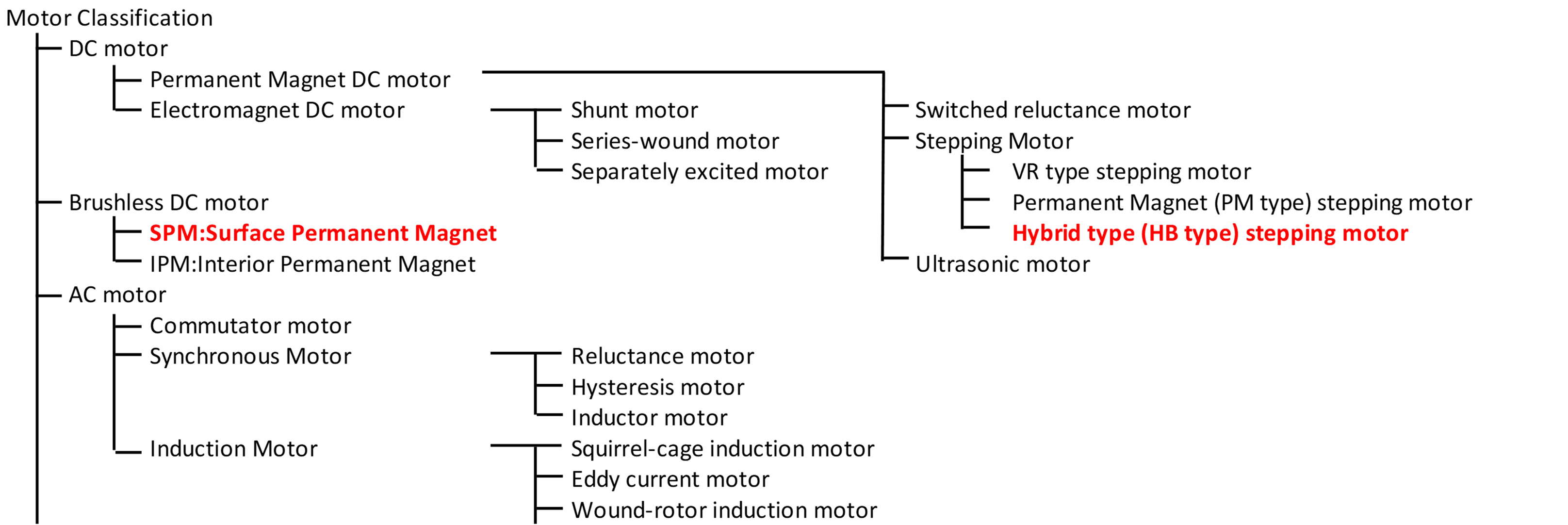 Many motor types exist, each with its own advantages. When we look at motors for positioning applications, ‘stepping motors’ and ‘servo motors’ rise to the top of the pack. Here are several applications where stepping and servo motors are utilized.
Stepping motors at their core are positioning motors, not requiring any outside feedback to position to a highly repeatable position. Stepping motors rotate by a fixed angle (step angle) based on the number of input pulse signals. For example, a motor with a 1.8° step angle rotates precisely 18° when given 10 pulses. This direct relationship between pulses and rotation allows for simple, precise control without feedback. Their mechanical structure enables them to hold a position without oscillation or dithering.
Servo motors do not have a mechanical structure to hold a position. Servo motors fundamentally operate as thrust (force for linear) motors. They use a closed-loop control to adjust position, speed, and torque based on real-time feedback from an encoder. This gives servo motors biggest advantage in that they actively correct errors to maintain accuracy under varying loads or high speeds. Because of this, they exhibit slight dithering (small oscillations between encoder counts) when holding a static position.
While steppers and servos serve different needs, it is possible to combine their strengths by adding an encoder and servo driver to a stepper motor, creating a hybrid system that leverages the stepper’s repeatable positioning with the servo’s closed-loop precision
|
Use |
Name |
Classification of the motor |
Control |
Speed |
Positioning resolution |
|
Speed control, positioning |
Stepping motor |
2 or 4-phase stepping motor |
Constant current control, constant voltage control |
0 ~ 3000rpm |
15° to 0.9° depending on the motor. |
|
Speed control, positioning |
Closed-loop stepping motor |
2 or 4-phase stepping motor |
Servo control |
0 ~ 3000rpm |
0.036 ° |
|
Speed control, high-precision positioning |
Servomotor |
Brushless DC motor surface magnet type |
Servo control |
0 ~ 3000rpm (Instant 5000rpm) |
0.000000059° (24bit) |
What makes a motor perform with such excellent positioning accuracy?
While both stepping and servo motors are excellent at positioning, they can not do it by themselves. They require a motor control system. What are the key blocks of the stepping and servo motor control systems?
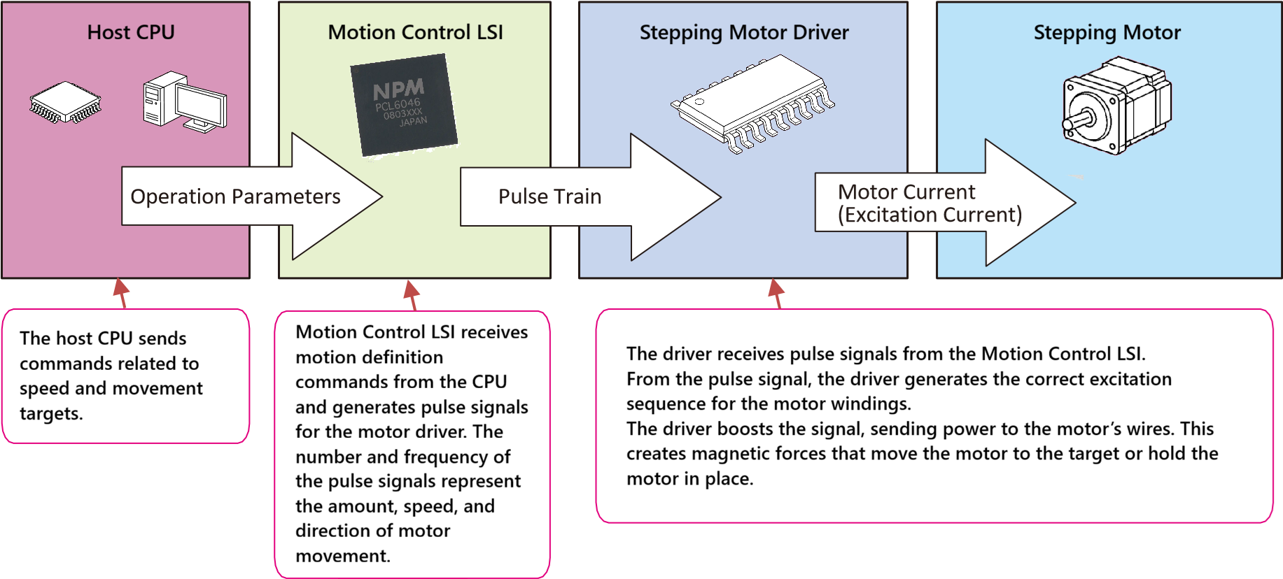
Stepping Motor Control System
Due to its internal structure, a stepping motor can hold its current position when excited (windings are energized) and rotates by switching the excitation, enabling precise positioning without sensors. To rotate the motor, a stepping motor driver switches the current direction to the windings according to pulse signals, with the switching order determining direction. Even when no pulses are applied, the windings remain energized to generate holding torque, allowing the motor to maintain position with high repeatability—stopping cleanly at a defined step without oscillation or dithering.
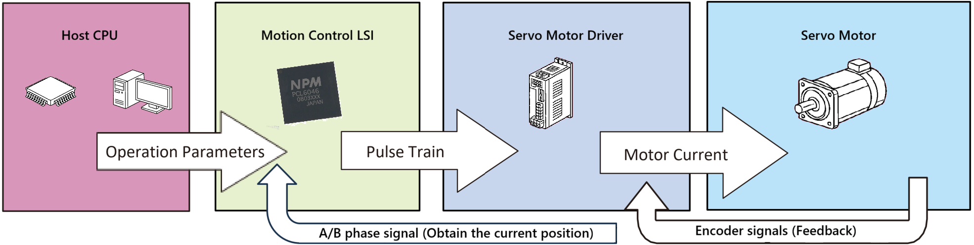
Servo Motor Control System
Servo motors generally operate at higher speeds and larger torque ranges than stepping motors. They use encoder signals as feedback for high-resolution, closed-loop control. The servo driver compares the motor’s current position (from the encoder) to the command position (pulse count input from the controller), adjusting the motor’s rotation to eliminate the difference—known as deviation or accumulated pulse error. Unlike steppers, which hold position statically, servo motors continuously regulate their position, often exhibiting slight dithering (small oscillations between encoder counts) when maintaining a fixed location.
Why use a Motion Control LSI?
In positioning control, to prevent problems such as position misalignment due to inertia, motors are gradually accelerated, driven at a constant speed, and finally decelerated to stop as shown in the upper part of Figure 1 (the horizontal axis is time, and the vertical axis is speed). When expressed as pulse trains, they become the pulse waveform shown in Figure 1. However, if you try to accurately generate pulses that change gradually over time using only the timer interrupts of a microcontroller, it will consume a large amount of the microcontroller processing resources.
![]()
Figure 1 : Motor speed transition... accurately generating pulses that gradually
change over time using only micro-controller timer interrupts is challenging.
In addition, attempting to handle output pulse counting, current position counting, deceleration start position determination, and limit-switch processing solely with a microcontroller is a significant burden. Considering these points, just using a pulse control LSI allows for efficient and precise control of positioning motors.
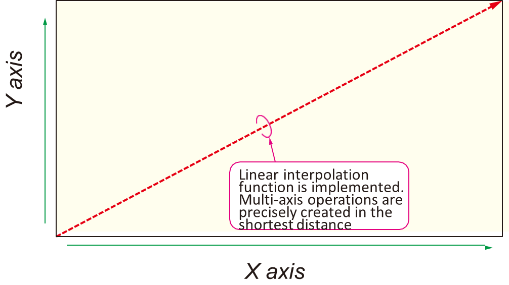
Figure 2 : Motion Control LSI can coordinate control of X and Y axes,
enabling easy creation of diagonal movements.
The Motion Control LSI, ‘PCL6046’, explained here also enables “linear interpolation” operation for 2 or more axes motors (Figure 2). This movement can be applied to XY tables used in manufacturing and inspection equipment, where the X and Y axes are synchronized to move diagonally in the shortest and most accurate path.
Easy way to get started with a Motion Control LSI in your system
Imagine a motion control solution so flexible that it adapts to your vision — not the other way around. A solution where prototyping and production speak the same language, where scalability isn’t a bottleneck, and where precision isn’t sacrificed for convenience. That’s the Commander Ecosystem.
The Commander Ecosystem, is a family of motion control products, (hardware, software, support, and design) built around a shared approach to motion control. The heart of which is the Commander Motion core, a secure, easy-to-use hybrid IC built around the Nippon Pulse ASIC, PCL6046, Motion Control LSI, and an ARM microcontroller.
The Commander Ecosystem hardware includes programmable motion control ICs for embedded design, standalone controllers for ready-to-deploy applications, and the new Control Max series, which integrates a servo controller and driver into a single system-level unit.
All Commander Ecosystem products share a common software platform, so code written for one transfers seamlessly to another — empowering you to prototype with agility and scale to production with confidence.
In section "Commander Ecosystem" we will dive deeper into the Commander Ecosystem and discover motion control that adapts to your vision.
We took you on a journey through the world of motion control—from the pulse-driven precision of stepping motors to the dynamic, feedback-driven power of servos. We explored how steppers dominate in open-loop applications where cost, repeatability, and simplicity matter, like in inkjet printers or medical syringe pumps. We saw how servos shine in high-speed, high-torque environments where adaptability is key, such as in CNC machines or robotic arms. And we uncovered the hybrid systems that blend the best of both worlds. But we also exposed a fundamental challenge: control complexity. Generating smooth acceleration curves, synchronizing multi-axis movements, and processing encoder feedback in real time can overwhelm even the most powerful microcontrollers. That’s where the motion control LSI steps in—not just as a helper, but as a game-changer. By offloading pulse generation, interpolation, and error correction to dedicated hardware like the PCL6046, an LSI frees your system to focus on what matters most: performance, precision, and reliability. But how do you harness this power in your own designs?
Now that you’ve seen the why behind motion control LSIs, the next section dives into the how—starting with the very foundation of stepping motors. This section will cover the details of PM and HB steppers, including windings, micro-stepping, and torque. Discover how these motors move in distinct steps and why their design ensures accurate, consistent placement. Learn how constant current control and micro-stepping transform a basic stepper motor into a precise tool. Ready to delve deeper?