Servo motors
Intro For servo motors
Structure and Mechanism or Motion: Servo Motors
Topics:
Servo motor systems enable high-precision positioning and speed control.
Structure of servo motors
Many modern high-performance servo motors are based on Brushless DC Motors. By removing brushes and commutators, this design prevents wear and electrical noise, ensuring a long and maintenance-free operation. The switching of electric current to the coils in motors achieves efficient and smooth rotation.
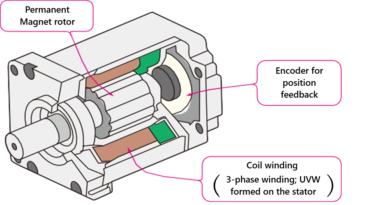
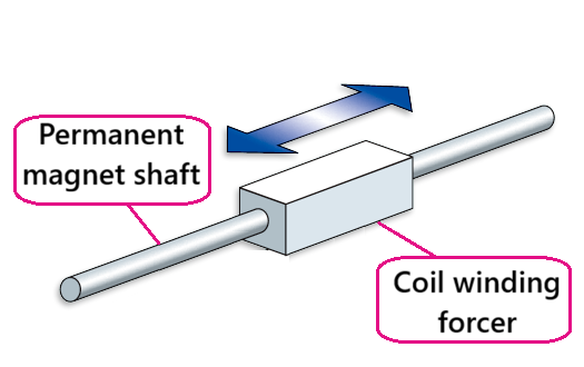
Figure 1 : Structure of servo motors
Stator / Forcer - Coil winding
The stator is a fixed part of a rotary servo motor, made of an iron core with coils wound around it. In coreless linear servo motor like the Linear Shaft Motor, the forcer is the moving part and only has the coil windings. The winding is 3-phase U, V, W which are connected in the most popular WYE (Figure 2) or a DELTA (Figure 3) configuration. By passing current through these coils, they become electromagnets and generate a moving magnetic field.
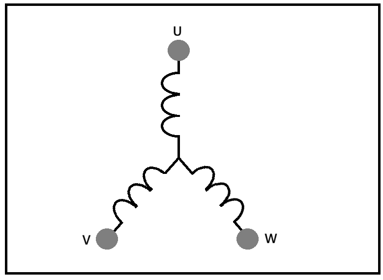
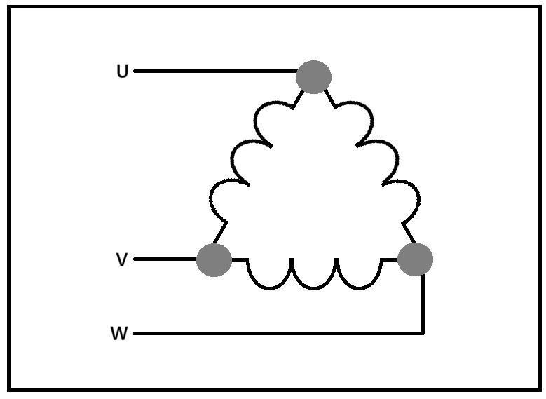
Figure 2 : WYE winding Figure 3 : DELTA winding
Rotor / Shaft - Magnet
On a rotary servo motor, the rotor spins, while on a linear motor like the Linear Shaft Motor, the shaft is usually fixed. These parts contain powerful permanent magnets. The movement of these motors is due to the push and pull between the electromagnets on the stator/forcer and the permanent magnets on the rotor/shaft.
Encoder - Detect position and speed
The greatest feature of servo motors is their precise feedback control. An encoder is essential for this purpose (Figure 1). An encoder, placed between the moving and fixed parts, and senses rotation or distance and speed, then changes this into electrical signals. The servo amplifier (driver) receives this information and corrects deviations from the target value in real-time. This allows the motor to accurately maintain the commanded position and speed even with external load variations. Because of this closed-loop control, many applications requiring high precision, such as industrial robots and machine tools, use servo motors.
Control method of servo motors
|
Control method |
Features |
|
Pulse Control |
Pulse amount controls position, and pulse speed controls speed. It is the simplest and easiest to understand. |
|
Analog Control |
Position control is managed by the higher-level controller, and speed control is managed by the command voltage (analog). The command voltage is susceptible to disturbances, which tends to make the control unstable. |
|
Serial-bus control |
Position and speed controls through serial communication called the fieldbus for the FA industry
Requirements for a higher-level controller To maintain high-speed communication, it is necessary to perform complex calculations such as position and speed within a few hundred microseconds in the fastest cases and transmit that data. Requirements for a servo motor It is necessary to receive, analyze, control, and transmit data from the higher-level controller within the communication cycle. |
Pulse control
The method to control the motor positions by pulse amounts as well as speeds by the frequency of pulse to the servo driver.
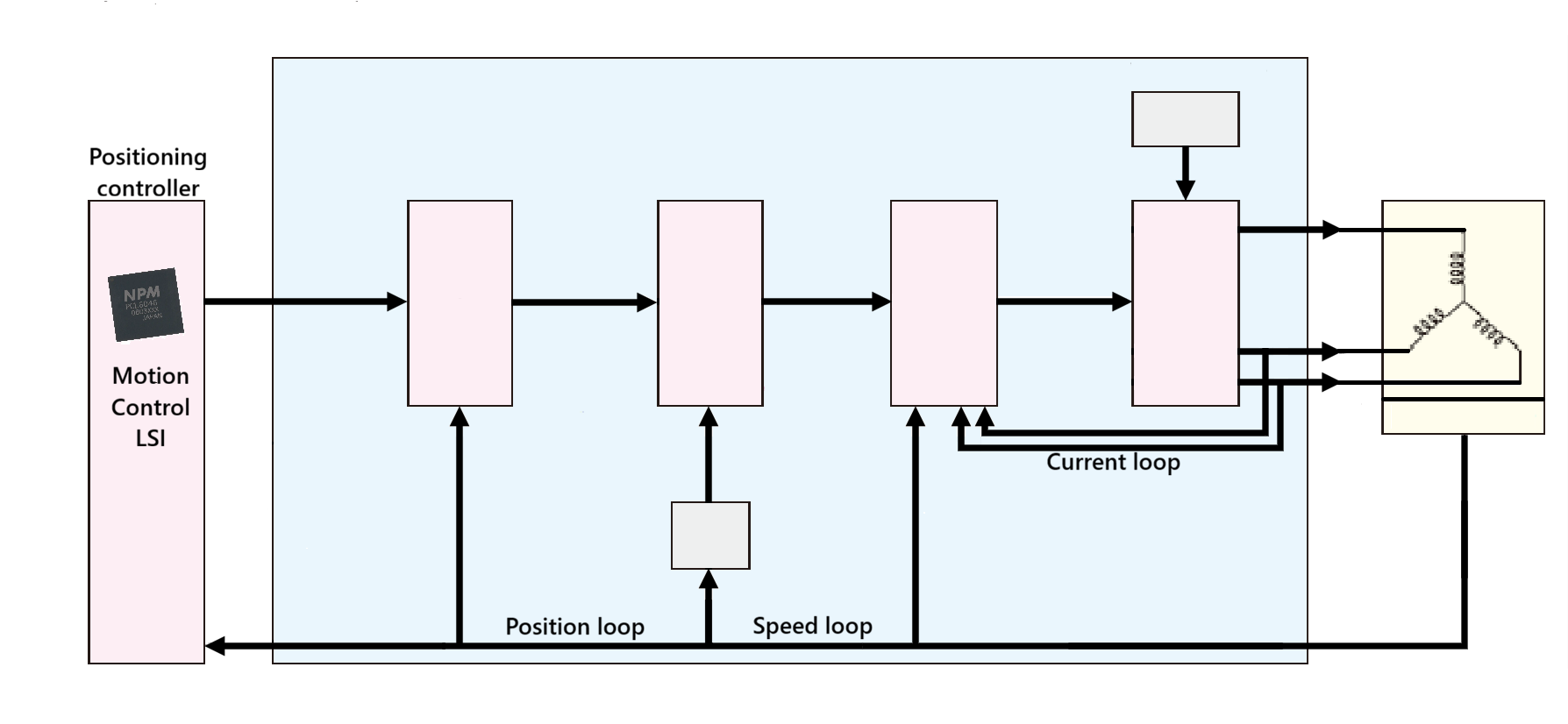
Figure 4 : Pulse control block
Analog control
In analog control, the accurate positioning of a motor itself is basically the role of a Positioning controller [Figure 5]. The servo amplifier only provides speed based on the command voltage. The information where the motor is positioned or whether the motor has reached the target position is determined by the positioning controller with reading the encoder feedback and calculations.
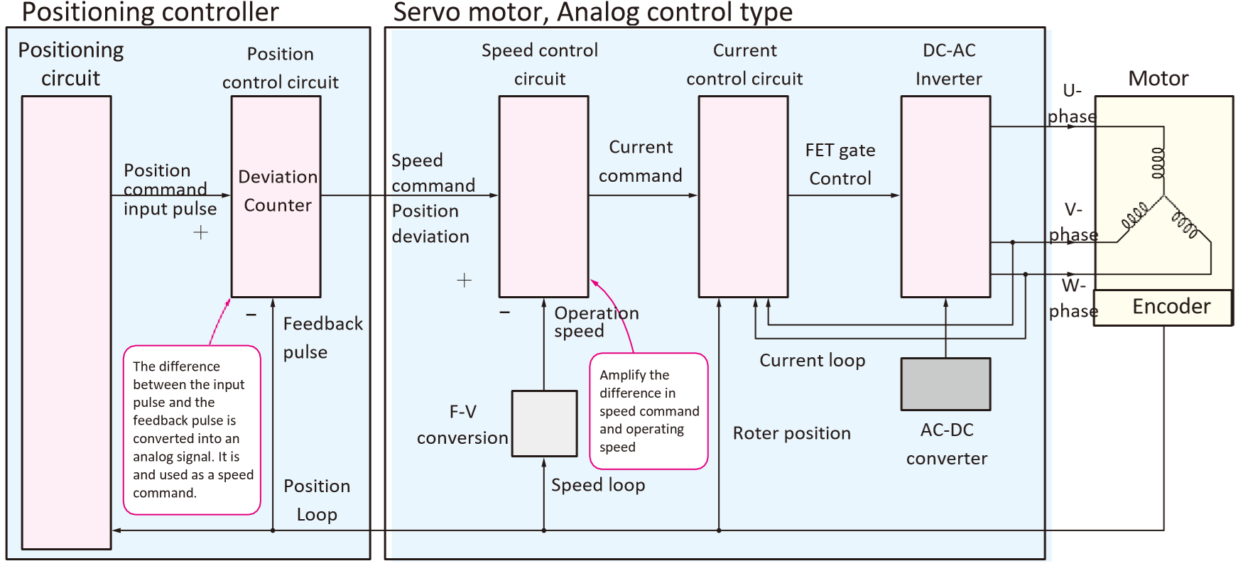
Figure 5 : Analog control block
Serial-bus control
The serial control method of servo motors uses field bus communication, which is popular in the factory automation industry, to control position and speed [Figure 6]. This enables reduced wiring and allows for complex multi-axis coordinated control.
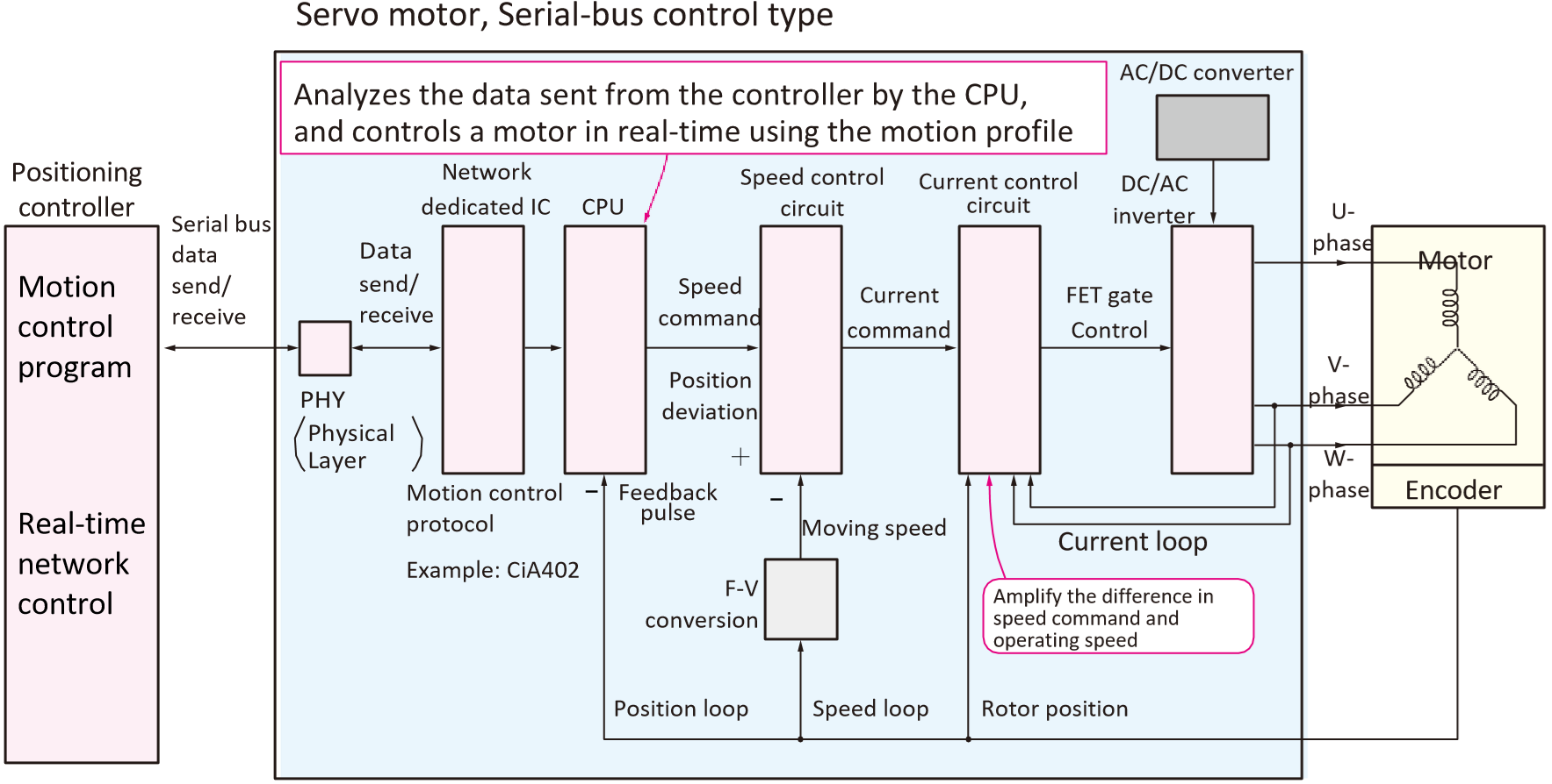
Figure 6 : Serial-bus control block
Elements of servo motor control
The drive circuit of servo motors is the essential element for achieving high-efficiency and precise control (Figure 7). The core of this circuit is to supply current to the motor’s U / V / W phases in the correct sequence.
Encoder
An encoder is essential for accurately acquiring the rotor position of a motor. An encoder tracks the rotor’s angle as it spins and sends this data to the servo amplifier’s control system.
Current control circuit
The rotor position information from an encoder and the current command from the higher-level controller (equivalent to the target torque) are input to a current control circuit. The current control circuit precisely monitors and adjusts the current flowing through each UVW phase to match the actual motor current with the current command. This constitutes the innermost current loop that determines the responsiveness and accuracy of control.
Power transistor
The output from a current control circuit is sent as FET gate control signals to the power transistor (FET) within the inverter circuit. By turning each FET’s ON/OFF, the power from a source is supplied to a motor’s UVW phase coils at the appropriate timing and amount. For example, by applying current to a specific UVW phase at a specific rotor position, torque is efficiently generated, allowing the motor to rotate smoothly
.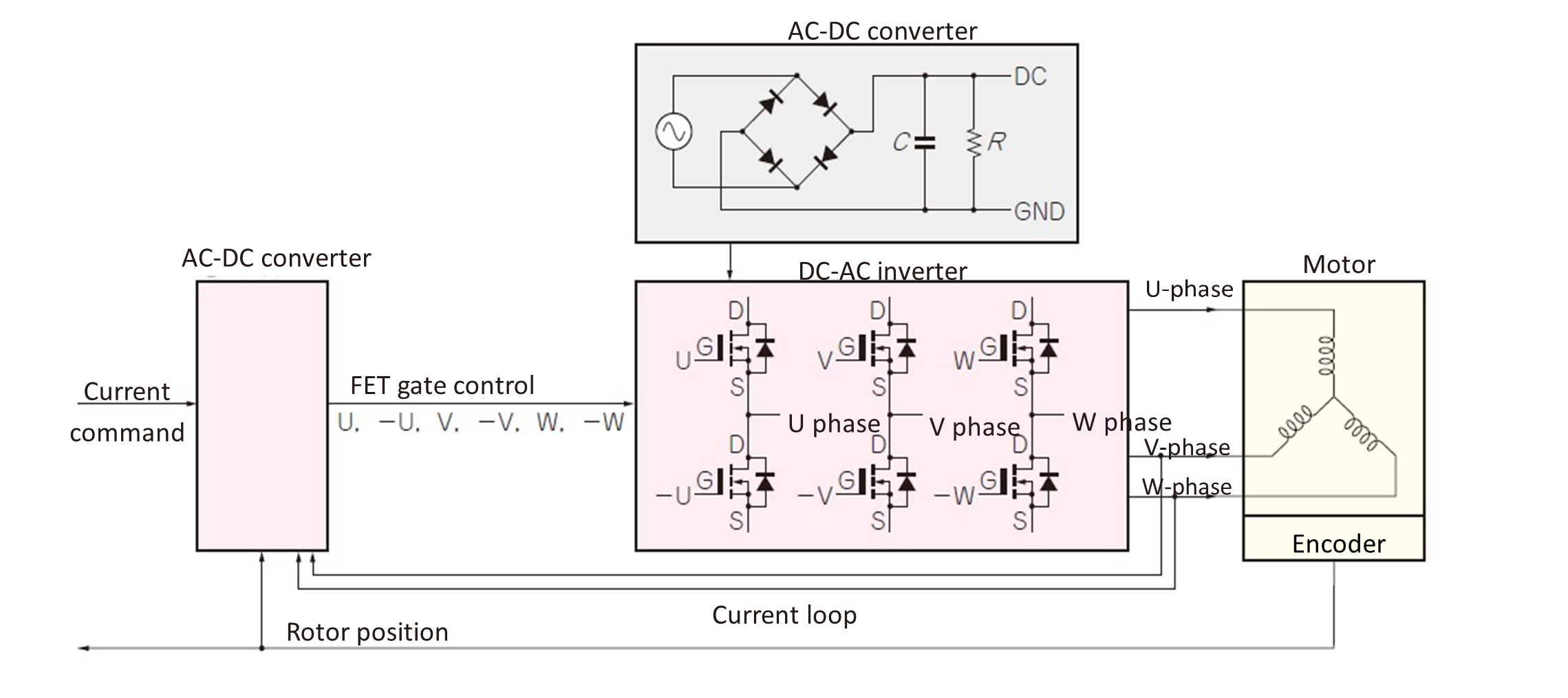
Figure 7 : Components in a Servo Motor system
Brushless DC motor
Most of the servo motors widely used in the industrial field adopt Brushless DC motors, which are known as “Permanent Magnet Synchronous Motor (PMSM)” as the motor component.
Drive sequence of brushless DC motors
For driving a brushless DC motor, it is popular to use the three phases: U-phase, V-phase and W-phase. This is because a brushless DC motor operates internally as a ‘3-phase AC motor’. These U, V, and W phases are arranged with the electrical angle difference of 120° between them (the mechanical angle difference varies depending on the number of poles in the motor). (Figure 8).
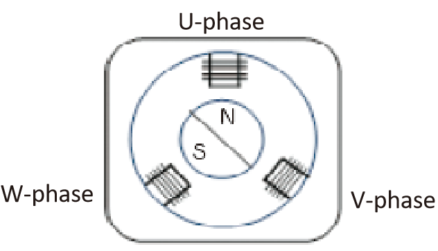
Figure 8 : Example of a motor to be controlled
(3-phase 2-pole)
In this section, an example of FET gate control for a 3-phase, 2-pole and 3-slot motor is shown (Figure 9).
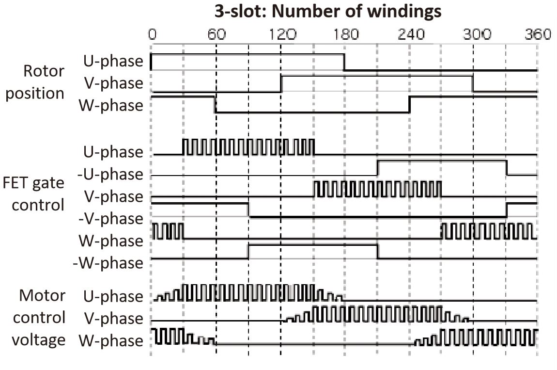
Figure 9 : Relationship between the rotor position and MOSFET gate control voltage
As the current is stepped through the phases of the stator coils, the magnetic field of the rotor synchronizes with the magnetic flux of the stator, causing rotation as seen in Figure 10.
Figure 10 : Current flow vs flux vector
Basic knowledge of PWM ( Pulse Width Modulation)
In this section, we will explain the PWM technology, which finds frequent use in the gate control of MOSFETs for brushless DC motors.
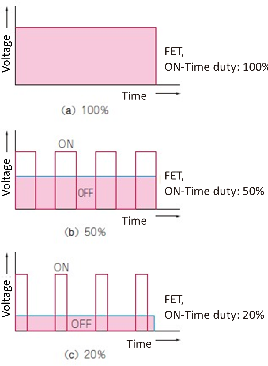 PWM (Pulse Width Modulation) is a technology that creates an analog average voltage from digital signals. In pulse signals with a constant cycle, the average voltage of pulse waveform is adjusted by changing the ON-Time (Pulse Width). For example, if the ON-Time is half of the cycle, the average voltage will be half of the supply voltage; if the ON-Time is longer, the average voltage will be higher, and if shorter, it will be lower (Figure 11). This ratio of ON-Time is called the “Duty Cycle”. Due to rapid ON/OFF switching, the inductance of a coil smooths the current in an inductive load like a motor, enabling smooth operations.
To create a sine wave, the ON-Time is lengthened (wider pulse width) at the peaks (high voltage sections) of the waveform and shortened (narrower pulse width) at the valleys (low voltage sections) (Figure 12).
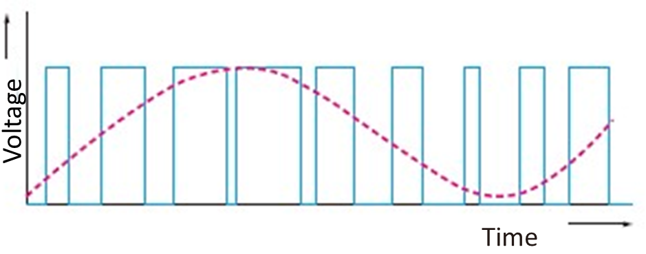
Figure 12 : AC voltage can also be created by PWM.
Changing the ON-Time of the FET changes the average voltage.
The created rectangular wave sequence contains a lot of high-frequency components (switching frequencies). Applying this wave sequence directly to a motor can cause significant noise and vibration. Therefore, an LC filter (coil and capacitor) is generally used to remove high-frequency components and extract a smooth AC waveform (close to a sine wave).
This makes sinusoidal control of the current passed through U, V and W phases is possible as shown in figure 13.
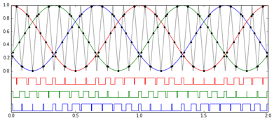
Figure 13 : Sinusoidal control with smooth flex vector
I am confused by Figure 14, the document reads that the LSI can generate this wave form, but I do not know how.
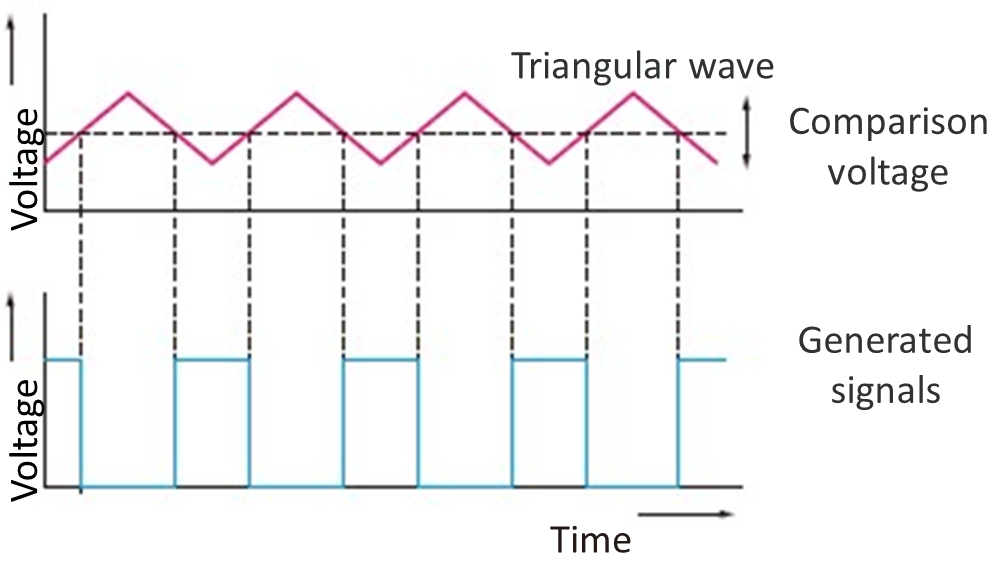
Figure 14 : How to generate PWM signals (works inside the LSI)
The time width changes by varying the comparison voltage against the triangular wave.