Basics of motor control
Intro for Basic of Motor control
Topics:
- Positioning motors operate at a specified angle in response to control commands
- Basic motion control operation patterns
- Examples of motion control operation patterns
- motion control; on-site ingenuity
- Output pulse signal requirements for drivers
- Control pulse specifications for drivers
- Servo interface
- Encoder signal counting method
- Incremental encoder
- Signals required for the Origin Return of motors
- Example of Origin Return operation
- Origin Return using the phase excitation origin of stepping motor drivers
- Software end-limit
- Manual Pulse Generator
- Incremental position and Absolute position
Positioning motors operate at a specified angle in response to control commands
Positioning motors have a function to stop precisely at a specified position (angle or linear distance) in response to the given control commands. They are widely used in situations where not only moving loads but also controling the position of the load precisely is required.
Angle positioning
The smallest angle that a motor can move at one time is called “Step angle”. This angle is determined by the design of a motor itself (such as machining accuracy) and the resolution of a device that detects a motor’s rotational position (such as a rotary encoder). The smaller the step angle is, the more precise the positioning can be. Figure 1 shows the moving angle when pulses are sent to a motor of 1.8° step angle.
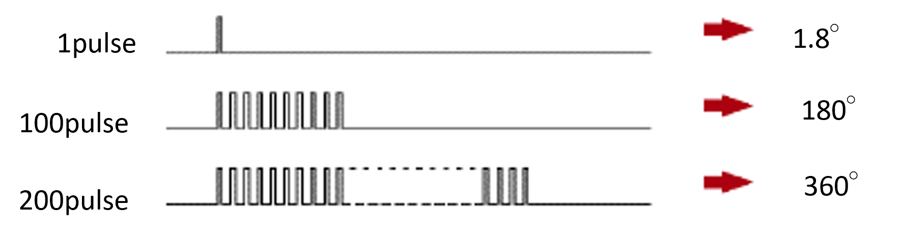
Figure 1 : Positioning by step angle
Speed control
The motor’s rotation speed (movement speed) is controlled by adjusting the speed at which these step angles are continuously moved using the control commands (Figure 2).
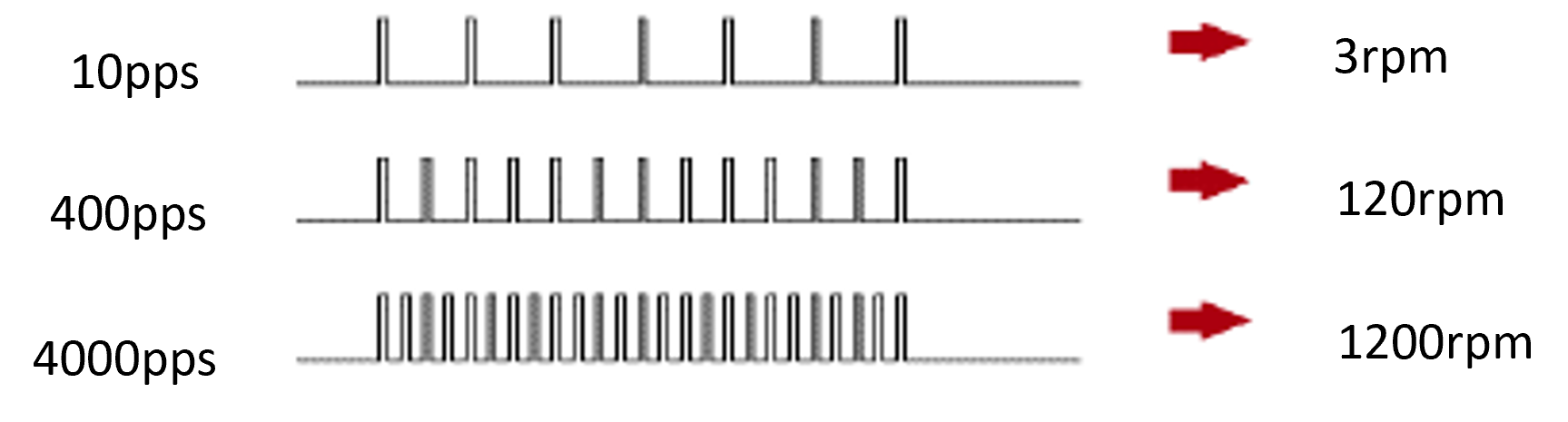

Figure 2 : Speed control ... The frequency of pulses given determines the rotation speed.
Basic motion control operation patterns
Linear acceleration/deceleration operation
When controlling a motor with pulse output, linear acceleration/deceleration is a pattern in which the speed (pulse frequency) increases linearly from the initial speed until it reaches a constant speed. Figure 3 shows the drive pattern.
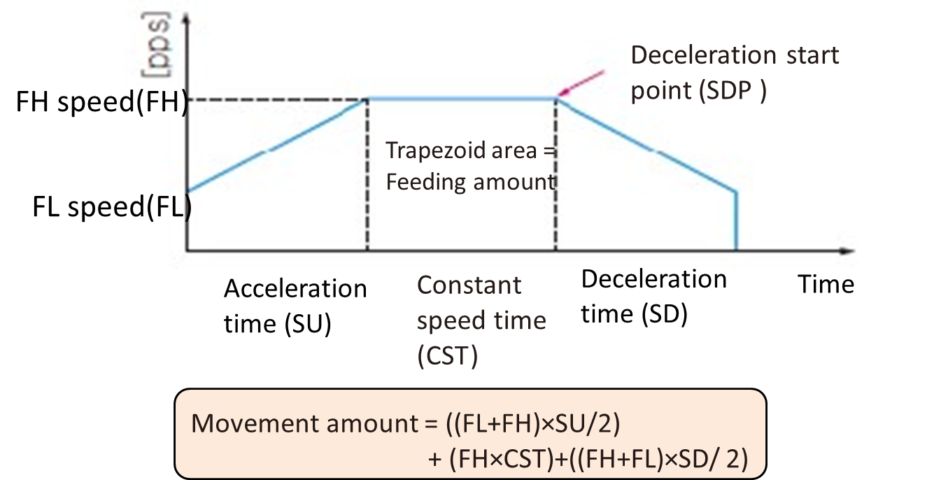
Figure 3 : The trapezoid area is determined by time × speed, and it shows the feeding (movement) amount.
In the case of stepping motors, FL (Frequency Low) speed sets the self-starting area, and FH (Frequency High) speed sets the pulse frequency for self-starting area or synchronous slewing area.
▶Acceleration phase
Initially, the pulse frequency begins to increase slowly, then increases at a constant rate. This allows a motor to accelerate smoothly. Figure 3 shows the section where the speed increases linearly.
▶Constant speed phase
Once reached the target speed (frequency) , the operation speed will be maintained. Figure 3 shows this phase in the horizontal part.
▶Deceleration phase
As the target position is approached, the pulse frequency is linearly decreased at the same or a different rate as during acceleration. This allows the motor to decelerate smoothly and stop at the target position. In Figure 3, this is the part where the speed decreases linearly.
FL speed
In the case of stepping motors, current is constantly flowing through the stator circuit. It creates an attraction between the rotor and stator, which generates the largest torque at start-up. Therefore, at startup, a certain speed (FL; Frequency Low) is given, and it operates at that speed.
Servo motors operate with a delay in response to commands, so they follow and operate more slowly compared to stepping motors.
Deceleration start point (SDP: Slow Down Point)
The deceleration start point is calculated to stop pulse output when FL speed is reached.
Differences in the motor operations
There are the following differences in the operations of stepping motors and servo motors in response to the position command pulses.
Servo motors operate systematically according to the deviation amount within the driver, resulting in a delay in response to commands. In contrast, stepping motors do not have a delay in response to commands. If a delay occurs, it means the motor is in out-of-step state (Figure 4).
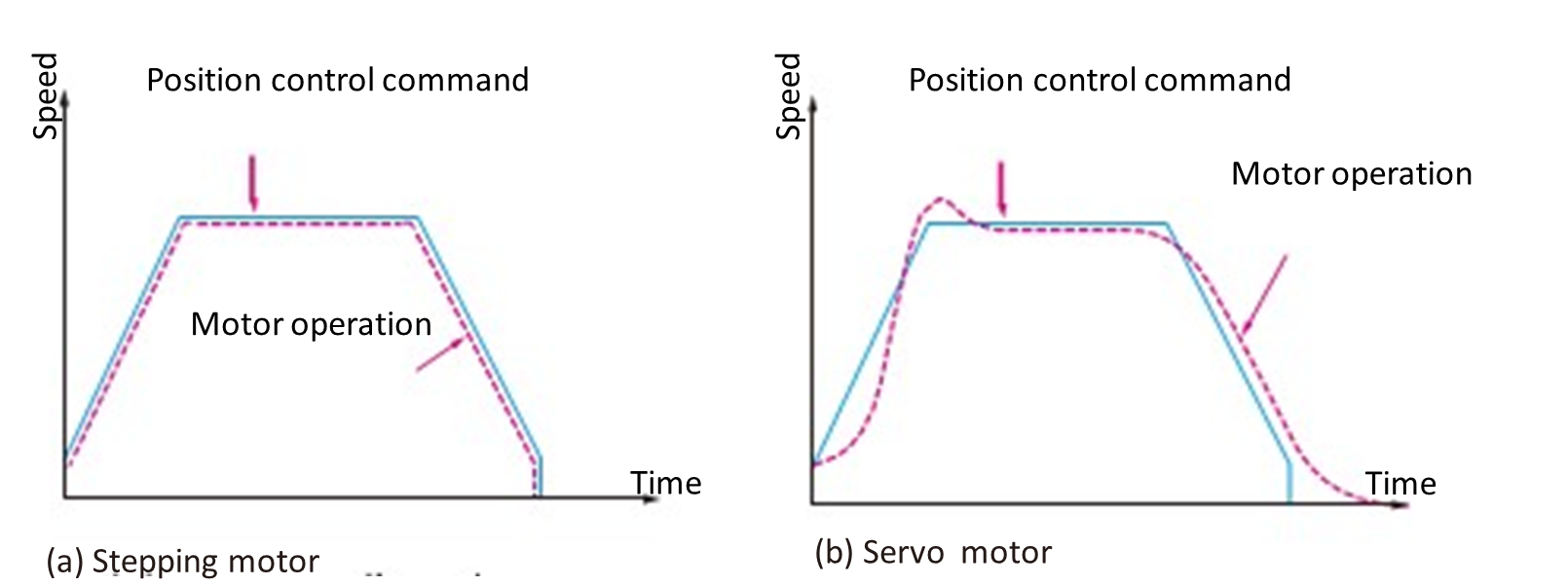
Figure 4 : Stepping motor vs Servo motor commanded position and speed vs actual
(a) Stepping motor ….Operation matching the position command
(b) Servo motor ….Operation with delay in response to commands
Example of motion control operation patterns
Preset operation (Positioning operation)
Operates at a predetermined feeding amount or rotation amount and stops.
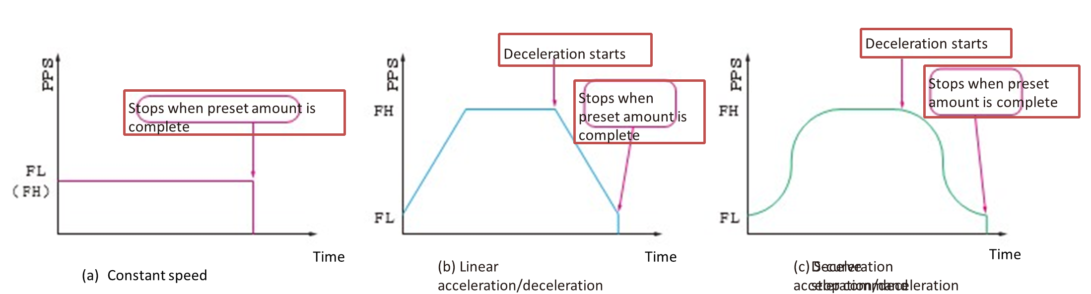
Figure 5 : Preset operation
Deceleration stop operation
When a deceleration stop command or deceleration signal is input during operation, deceleration begins at that point and stops when the FL speed is reached.
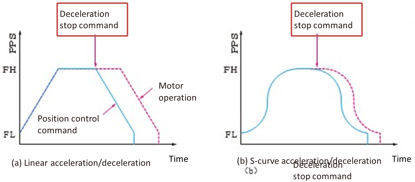
Figure 6 : Deceleration stop operation
Immediate stop operation
When an immediate stop command or an immediate stop signal is input during operation, the operation stops immediately regardless of the LSI’s operating state.
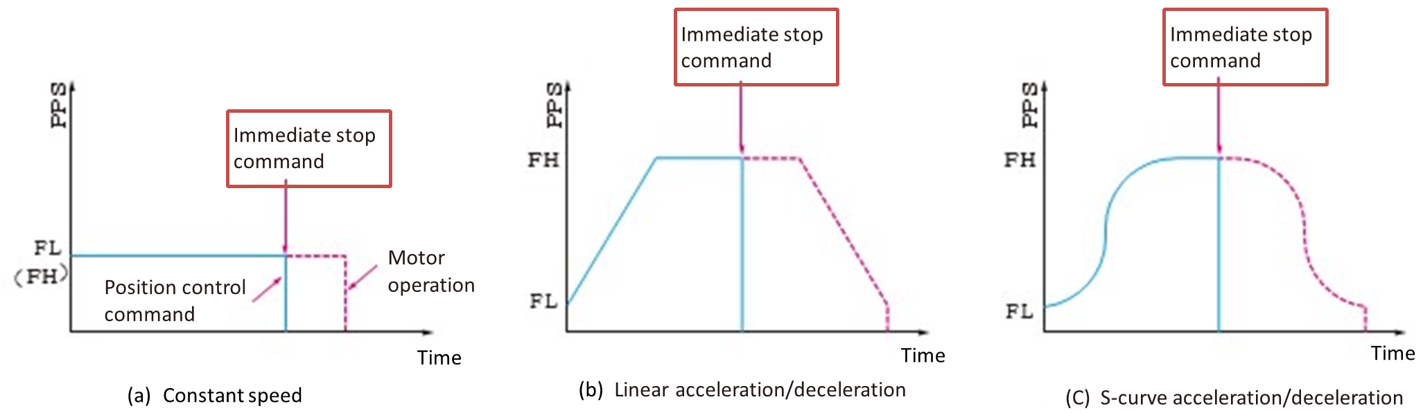
Figure 7 : Immediate stop operation
Origin return operation (Figure 8)
Origin return methods can be selected based on the conditions such as placements of origin (ORG), slowdown (SD) and end-limit (EL) signals, and the combination with the encoder Z-index signal.
▶Examples of origin return operation
- Slow-down (SD) OFF → ON to start deceleration ①, Origin (ORG) OFF → ON to stop ③
- Slow-down (SD) OFF → ON to start deceleration ①, Origin (ORG) OFF → ON to start counting encoder Z-index ②, Stop at Z-phase count-up ③
- Origin (ORG) OFF → ON to start deceleration ①, Decelerate to FL speed and stop ③
- Origin (ORG) OFF → ON to start deceleration and counting encoder Z-index ②, Stop at Z-index count-up ③
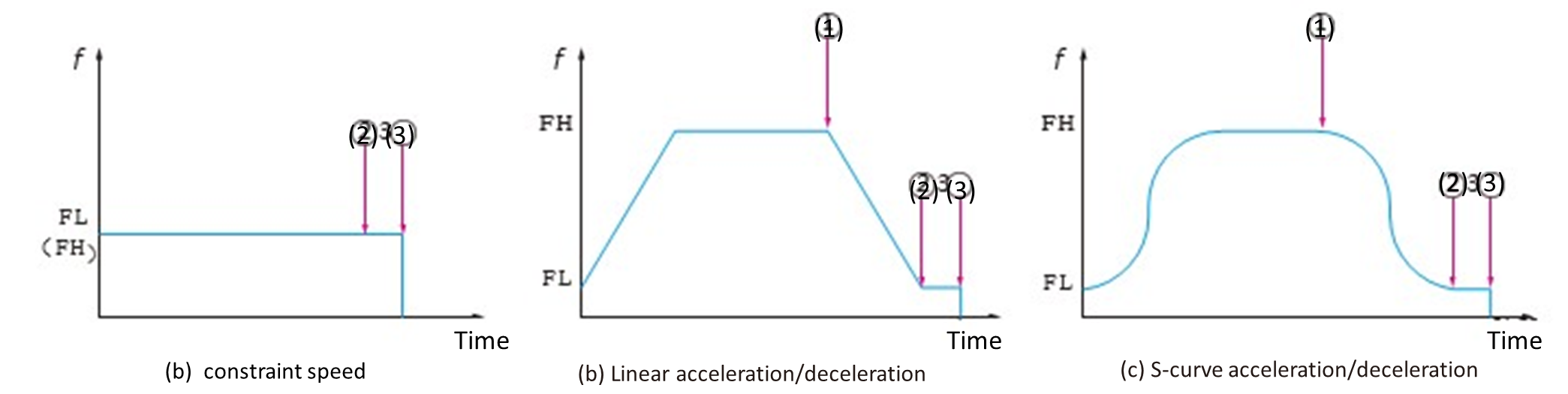
Figure 8 : Origin return operations
Examples of acceleration/deceleration patterns (Figure 9)
There are various patterns of acceleration/deceleration. In linear acceleration/deceleration, there are patterns where the acceleration and deceleration duration times vary. In S-curve acceleration/ deceleration, there are complete S-curve acceleration/deceleration without linear sections and acceleration/deceleration including linear sections. There are also patterns that combine S-curve acceleration and linear deceleration.
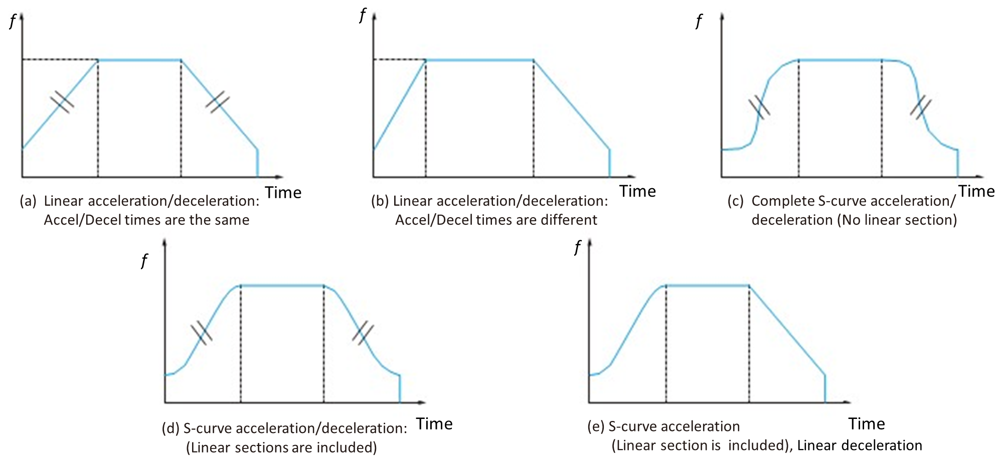
Figure 9 : Examples of acceleration/deceleration patterns
Motion control; on-site ingenuity
In servo motors, the gain adjustment can shorten the settling time, but it often requires a significant amount of time for adjustment. In that point, it is more effective to reduce vibration by smoothing the command from the control side, like in S-curve deceleration (Figure 10).
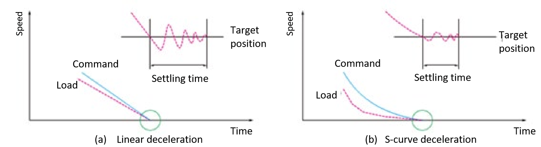
Figure 10 : Shorten settling time of load with S-curve deceleration
By incorporating a linear section into S-curve acceleration/deceleration, the acceleration rate can be kept low, minimizing load fluctuations (Figure 11).
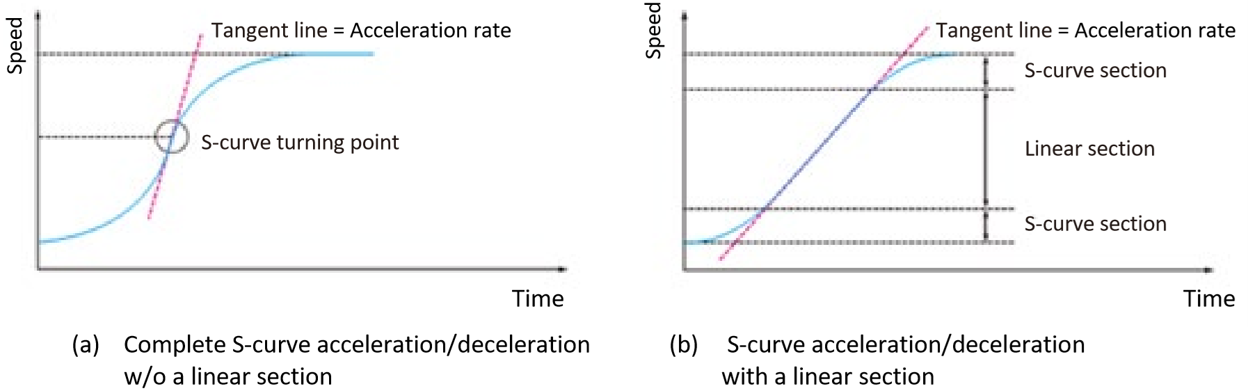
Figure 11 : Comparison of S-curve acceleration/deceleration and S-curve acceleration/deceleration with linear section (Jerk control)
Triangle drives can occur when FH (Frequency High) speed is too high relative to the feeding amount, or when the feeding amount is too small relative to FH speed. This drive causes a sudden rotation change toward deceleration during acceleration, delivering a significant impact to the load. To avoid this, triangle drive avoidance function is used. (Figure 12).
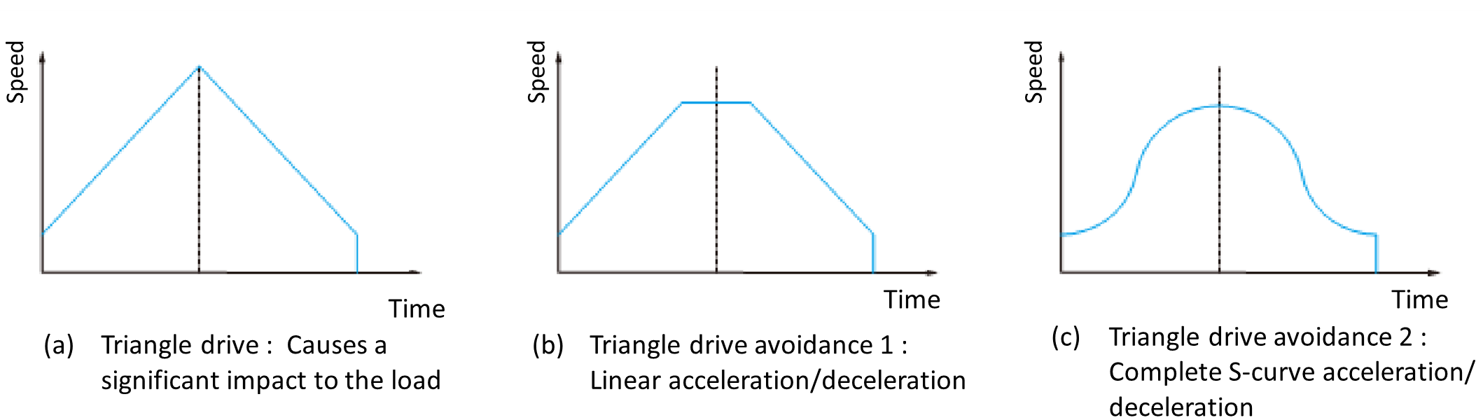
Figure 12 : Triangle drive avoidance
Output pulse signal requirements for drivers
The output pulse signals to the motor driver are very important for precise motor control.
Pulse output accuracy and speed ripple
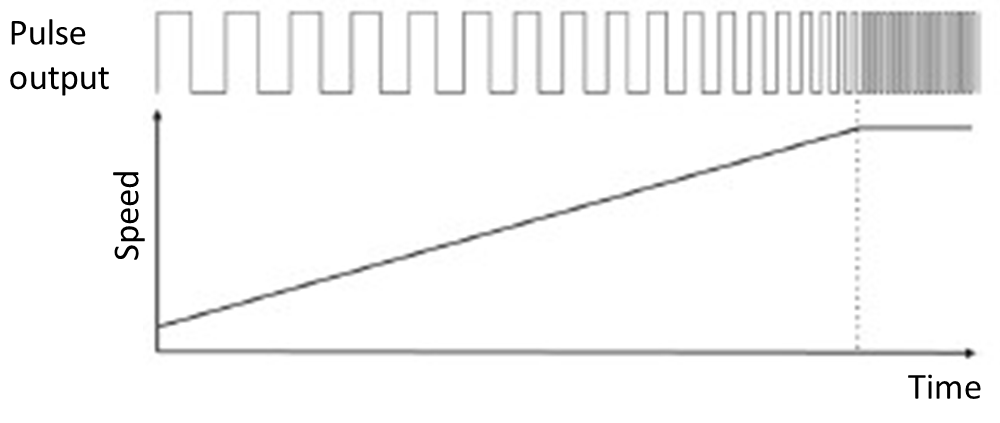
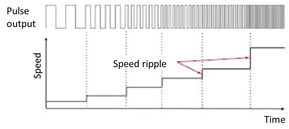
To move a motor smoothly, it is required to output the pulse resolution from the motion control devices finely, continuously, and smoothly (Figure 13). If the pulse output is “coarse,” specifically if the pulse intervals are uneven or the pulse width variations are large (Figure 14), small fluctuations occur in the motor speed, creating “Speed Ripples.” When speed ripples occurs, it can cause the motor operation to be jerky, and may lead to vibration or noise.
|
Figure 13 : Output pulses are continuous and smooth |
Figure 14 : Rough pulse outputs can cause speed ripple |
Duty cycle and pulse width requirements
The duty cycle of pulse signals (the ratio of time ON) should also be considered. Generally, for stable signal transmission, it is recommended to output with the duty cycle close to 50% (Figure 15).
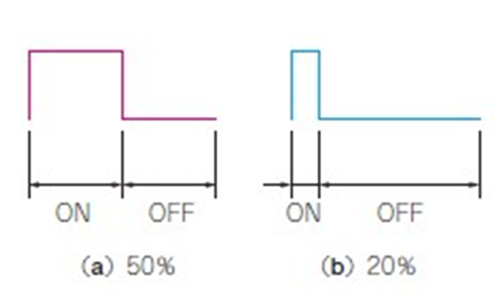
Figure 15 : Duty Ratio
Furthermore, the width of pulse signals (the pulse width) is also important. If the pulse duty width is extremely short, the high-speed photocoupler inside a servo driver or a stepping motor driver may not be able to accurately receive signals (Figure 16). Photocouplers are components that use light to insulate and transmit signals, but very short pulses may not sufficiently follow the ON/OFF of light. As a result, the signals may not be recognized.
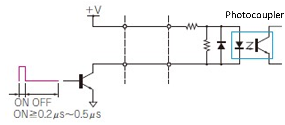
Figure 16 : If the pulse signal widths is too short, they may not be received properly by the driver
Control pulse specifications for drivers
There are three types of control pulse specifications for a driver as follows.
Common pulse mode (Pulse and Direction)
Pulse signals are output from the OUTn pin, and direction signals are output from the DIRn pin. (Figure 17).
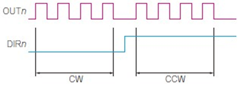
Figure 17 : OUTn and DIRn signals in the Common pulse mode (Pulse and Direction)
2-pulse mode (CW/CCW)
Plus direction pulse signals are output from the OUTn pin, and Minus direction pulse signals are output from the DIRn pin (Figure 18).
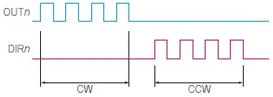
Figure 18 : OUTn and DIRn signals in the 2-pulse mode (CW/CCW)
▶Note 1... Mode confirmation
If pulses are output in the 2-pulse mode to a driver which is set in the Common pulse mode, the motor rotates only in one direction.
▶Note 2...Logic
If negative logic pulses are input to a driver set in the positive logic setting, a motor rotates in the reverse direction. Additionally, the motor will unintentionally move for one pulse when the power is turned ON.
90° phase difference mode
▶Direction
When the output of OUTn pin is 90° ahead in electrical angle compared to DIRn pin output, it indicates CW (clockwise) rotation [Figure 19(a)].
On the other hand, when the output of OUTn pin is 90° behind in electrical angle compared to DIRn pin output, it indicates CCW (counter-clockwise) rotation [Figure 19(b)].
▶Number of pulses
In the 4 times multiplication, the rise and the fall of OUTn pin output and the rise and the fall of DIRn pin output are individually counted as pulse outputs.
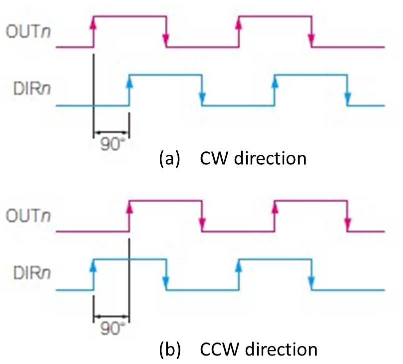
Figure 19 : OUTn and DIRn signals in the 90° pulse mode
Servo interface
When controlling a servomotor, the following signals are required in the servo driver (Figure 20). Here, we explain from the perspective of the motion control device shown on the left side of Figure 20.
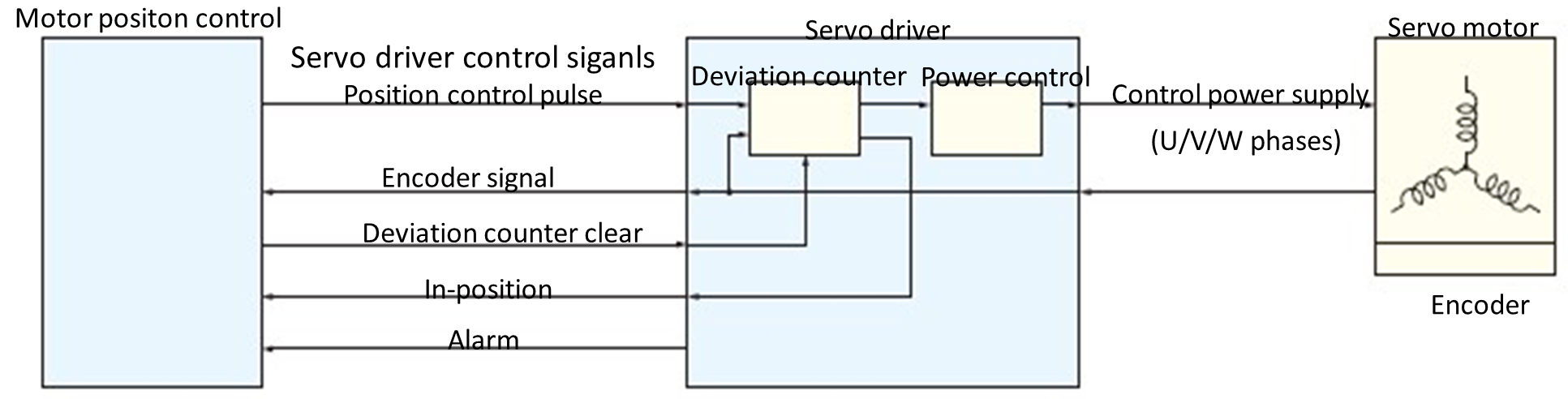
Figure 20 : Connection between motor position control LSI and servo driver
(1) Position command pulse output
“The number of pulses = position, and the pulse frequency = speed” are commanded by the pulse output to the servo driver.
(2) Deviation counter clear output
Inside the driver, the deviation counter counts the deviation between the position command pulse and the feedback pulse. When a position command pulse is input to the servo driver, the input pulses accumulate in the deviation counter, and as the motor rotates, the feedback signal subtracts the accumulated pulses in the counter. The servo motor rotates according to the accumulated pulse amount in the deviation counter and stops when the accumulated pulse amount becomes 0 (Figure 21).
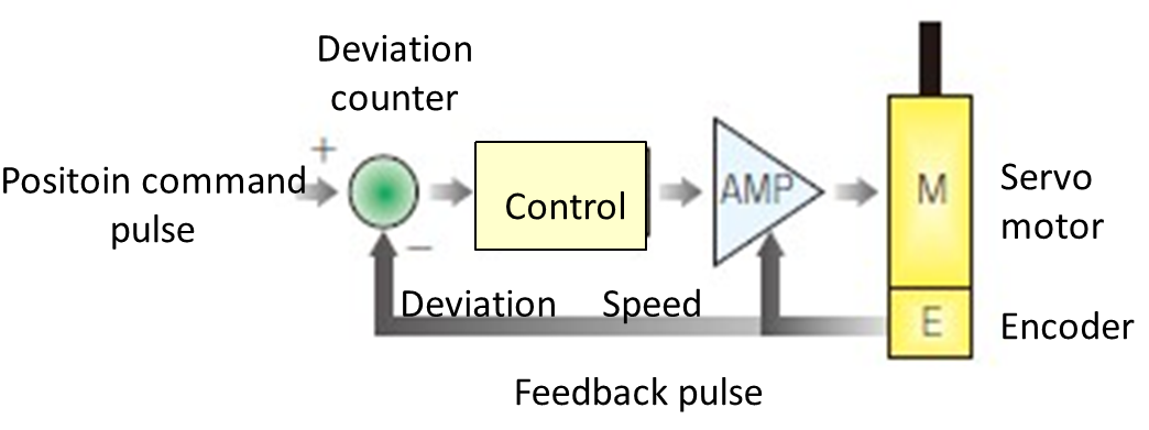
Figure 21 : Deviation counter accumulates deviation (pulse)
During origin return operation, the deviation counter is cleared to prevent passing the origin position due to accumulated pulses when reaching and stopping at the origin sensor position. Additionally, if an emergency stop is required for the servo motor, clearing the deviation counter will cause an immediate stop.
(3) In-position input
In-position is the positioning complete signal from a servo motor driver. A servo motor operates based on the accumulated pulse amount of the position command pulse and feedback pulse, so in response to the position command, the servo motor always operates with a delay (Figure 22).
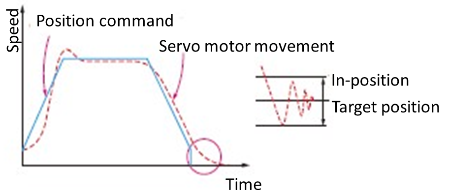
Figure 22 : In-position signal is output when the servo driver’s deviation counter is within the specified pulse range
In-Position signal is output when the deviation counter of the servo driver enters the specified range of pulses. The motion control device determines that the motor has completed its movement based on this signal.
(4) Alarm input
An alarm signal is output when any alarm issue occurs. The motion control device stops the position command pulse output when this signal is input during operation.
(5) Encoder signal input
This signal tells the actual position and speed at which the motor operated in response to the position command pulse.
Encoder counting method
Encoders usually output 2-phase signals (A-phase and B-phase) with 90° phase difference. To accurately detect position and rotation amount using these signals, the counts are extracted using the multiplication processes shown in Figure 23.
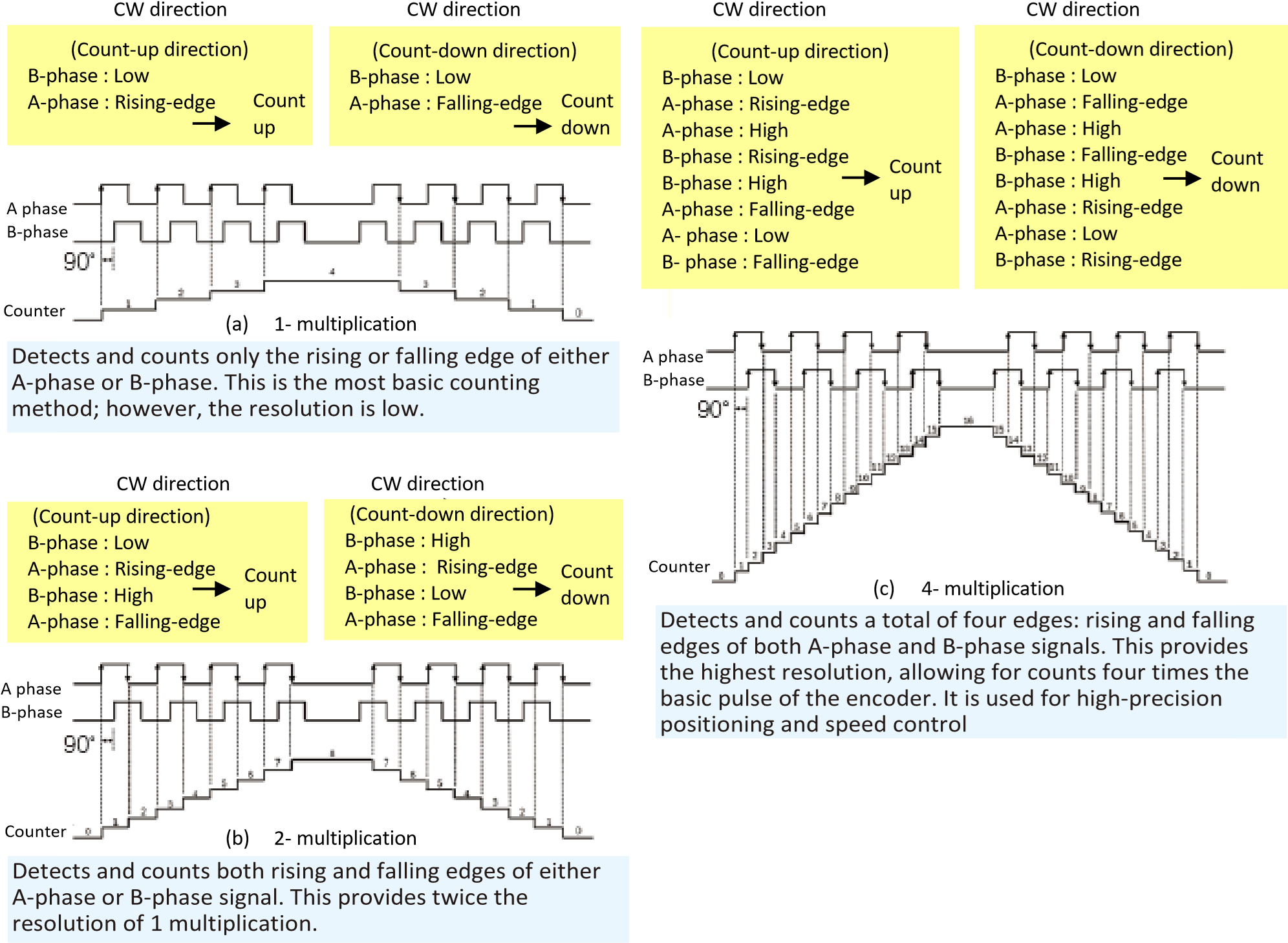
Figure 23 : Extracts the counts through the multiplication processes
Incremental Encoder
Fixed slits are arranged to create a 90° phase difference with rotating slits (Figure 24).
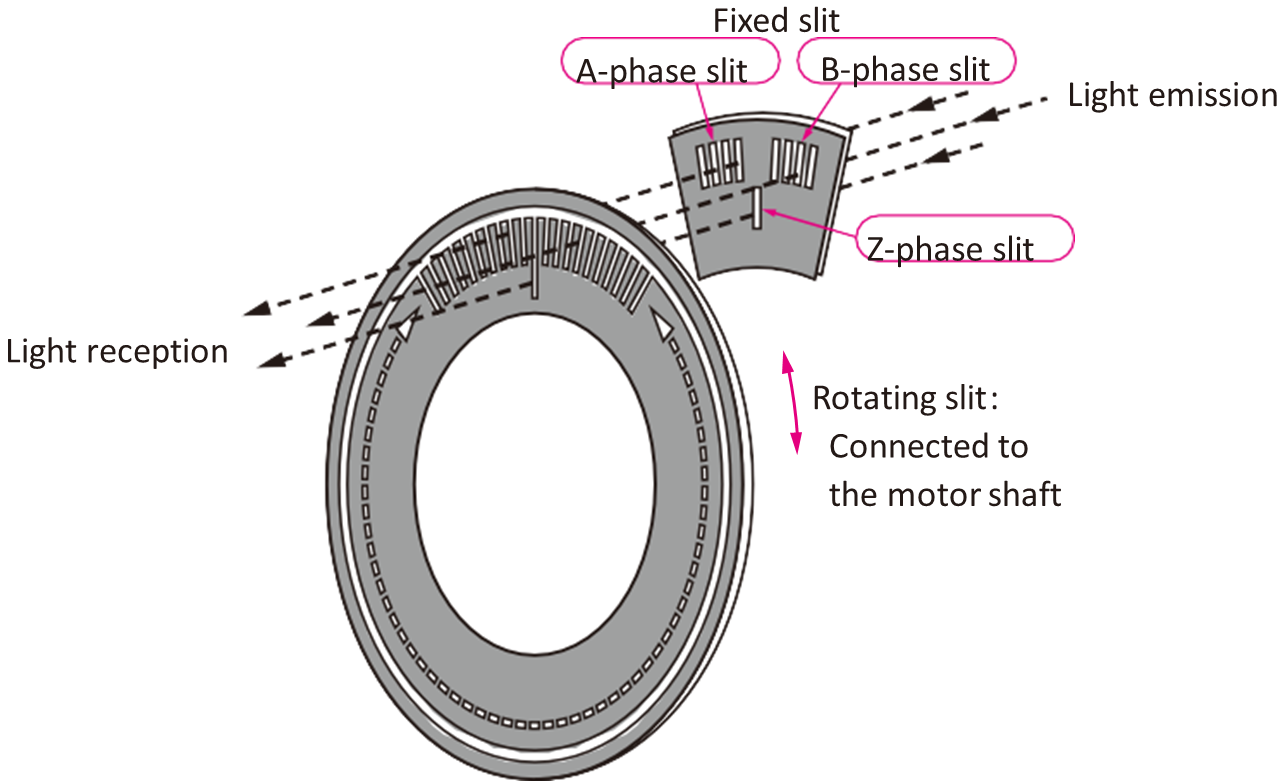
Figure 24 : Incremental encoder
Overview of operation
An incremental encoder is a sensor that detects changes in rotations or linear movements. Inside the encoder, a disk or a scale which has evenly spaced slits (grooves or holes) is placed and is read by the light emitting element and the light-receiving element.
When a motor shaft rotates or moves, the light is blocked or passes through these slits, generating pulse signals. Usually, two pulse signals: A-phase and B-phase, are output, and they have a 90° phase difference between them. By detecting the order of this phase difference, the rotation or movement direction can be determined. Additionally, in many cases, there is a Z-phase origin signal that is output once per rotation (or a certain distance).
Measures incremental movement or rotation amount
An incremental encoder measures incremental movement or rotation amount, not the absolute position at that moment, by counting pulses from a reference point. Therefore, when the power goes off or the system is started, the Origin-return operation (movement to the reference position and pulse count reset) is required. However, due to its simple structure, low cost, and ability to handle high-speed rotation, it is widely used for motor speed controls, rotation direction detection, and simple positioning controls.
Absolute encoder to detect the absolute position
In addition to incremental encoders, absolute encoders (absolute position encoders) are available. They can always detect the absolute position of a rotating axis. Since it retains position information even when the power is OFF, the origin-return is not required upon restart. A disk with multiple tracks is engraved with unique code patterns (e.g., gray code, binary code, etc.), and the combination of signals from each slit outputs the absolute position at that moment as digital data.
Signals required for the Origin Return of motors
Many manufacturing devices include motors and encoders for position controls. Especially, when using incremental encoders, the encoder can only detect the incremental movement amount of “how much it moved”, not the absolute position of “where it is positioned now.”
The purpose of the Origin Return is to match the mechanical position and motor position control. The following switches (or sensors) are located around the single-axis table system. (Figure 25).
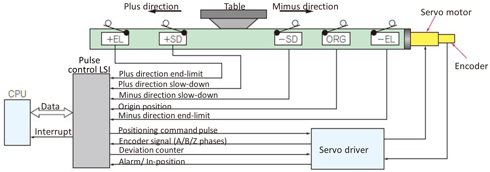
Figure 25 : Signals required for origin return
Plus direction end-limit, Minus direction end-limit
These switches stop the operation to prevent damage to the signal-axis table system.
Plus direction slow-down, Minus direction slow-down
These switches will slow down a motor so as to increases the positioning sensitivity to detect the origin position.
Origin position
A switch or a sensor indicates the reference position of a mechanical system. Upon detecting the signal, the system recognizes the current mechanical position and uses it as the reference point for subsequent movement amounts. Usually, it is detected in the final stage of origin return operation, and is used for resetting the position counter or setting a new reference point.
Index Z-channel
This signal is output once per motor rotation. This signal is used to improve the origin position accuracy.
Deviation counter clear
This signal resets the servo driver’s deviation counter, preventing positioning errors.
These switches and signals are used to perform the origin return operation. There are several patterns for this operation depending on the structure of a single-axis table. Also, position repeatability is required, so this operation is controlled by hardware.
Example of Origin Return operation
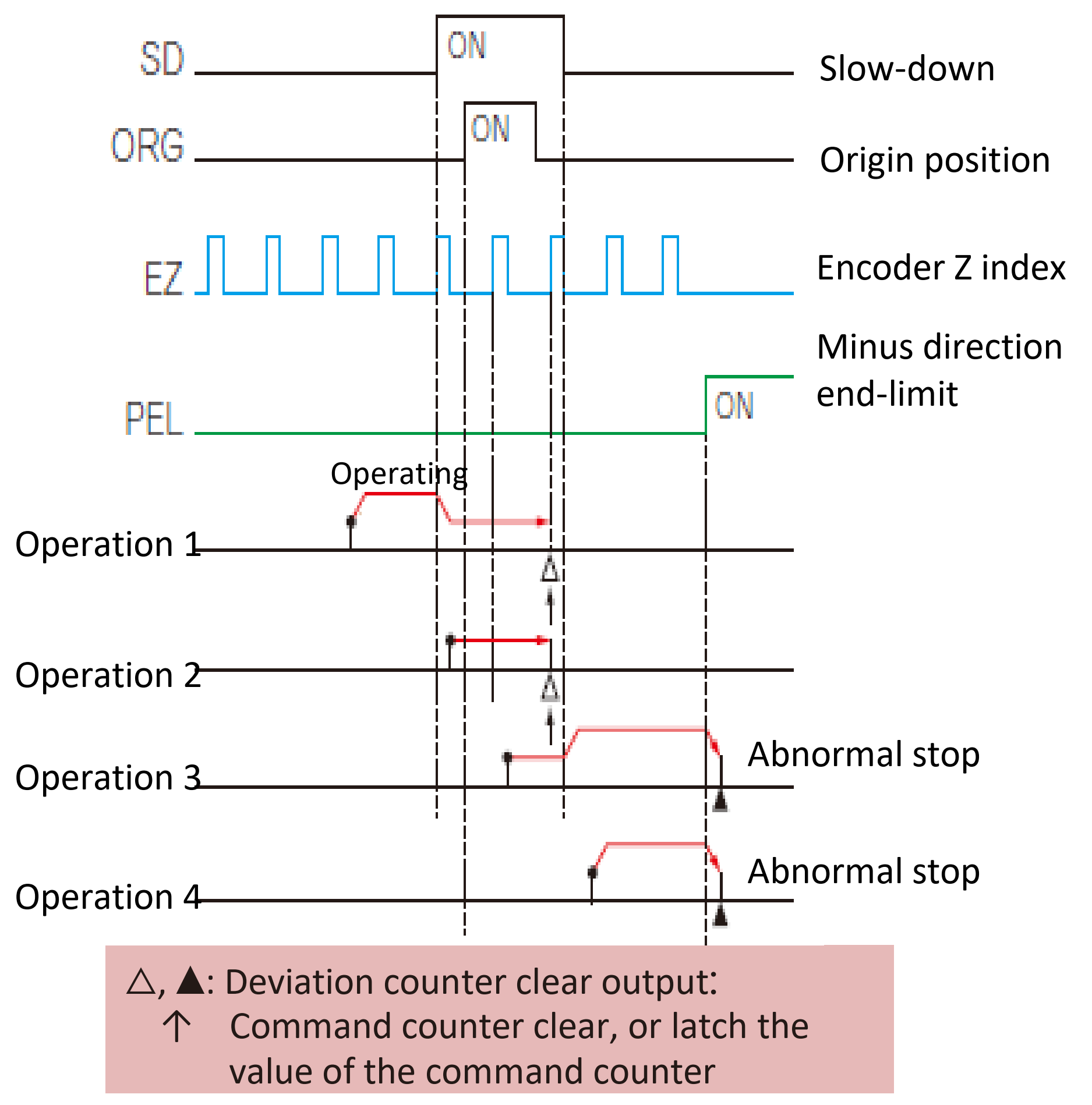 General motion control devices have several types of origin return operation patterns prepared in advance based on the signals required for origin return. Here, we will take an example of origin return operation prepared by the motion control LSI and explain its operation pattern with the schematic diagram (Figure 26 to right).
In this diagram, the black circle indicates the movement starting point, and the arrow indicates the operation stop point.
- Operation 1: From the left-side of the origin, slow-down OFF, origin OFF position
When the slow-down signal (SD) turns ON, a motor decelerates from the current speed to FL speed (starting speed or low speed). Then, after detecting the rising edge of the origin signal (the moment it turns ON), the output of position command pulses to the motor will stop at the second rising edge of Z-index signal, which detects one rotation of the encoder. At the same time, it clears (sets to 0) the internal position command counter in the control system and outputs a deviation counter clear signal to the servo driver. The count number of the Z index signal can be changed by the environment settings.
- Operation 2...From left-side of origin, slow-down ON and origin OFF
Since the slow-down signal (SD) is ON, it starts moving at FL speed without acceleration. The subsequent operation is the same as operation 1.
- Operation 3...From the position where slow-down ON and origin ON
The operation starts with both the slow-down signal (SD) and the origin signal (ORG) are ON. Since the slowdown signal is ON, the motor moves at FL speed. Although the origin-signal (ORG) is ON, the rising edge of the origin signal is not detected, so the motor continues to move in the minus direction.
After that, when the motor moves out of the area where the slow-down signal (SD) is ON, the speed will change to FH speed (high speed). Finally, when the minus direction end-limit signal (-EL) is detected, the motor decelerates and stops at FL speed. At this time, since it stopped due to the end-limit signal input, it is judged as an abnormal stop, and the interrupt bit turns ON.
- Operation 4...From right-side of origin, slow-down OFF and origin OFF
When the operation starts, a motor initially accelerates to FH speed. It continues to move in the minus direction, and it decelerates and stops at FL speed when the minus direction end-limit signal (-EL) is detected. At this time, since it stopped due to the end-limit signal, it is judged as an abnormal stop, and the interrupt bit turns ON.
Origin Return using the phase excitation origin of stepping motor drivers
The phase excitation origin output (initial excitation state indicating signal) is useful to ensure more reliable homing; origin return operation, of stepping motors. Stepping motors are driven by switching the direction of current flowing to each phase, and a signal is output each time when this current flow sequence (order) completes one cycle, which is called “Phase excitation origin signal (EORG) “(Figure 27).
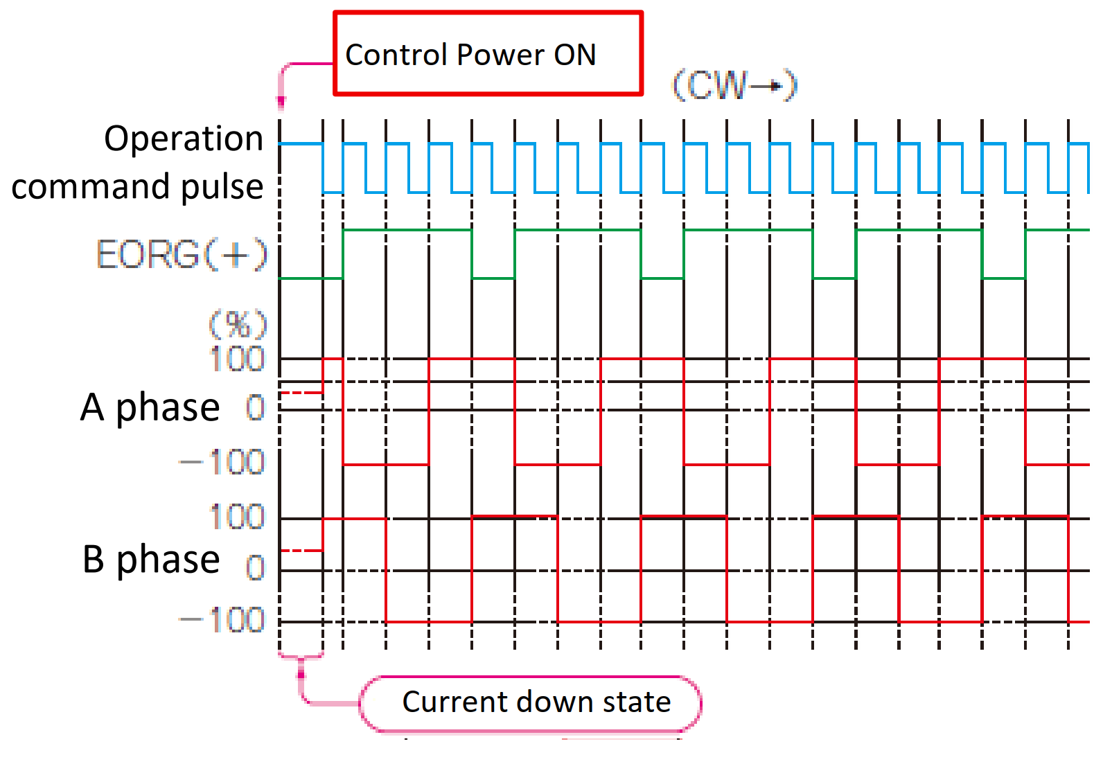
Figure 27 : Phase excitation origin output signal - EORG
When the power is supplied to a driver, the sequence starts and an EORG signal is output from the driver. Each time a command pulse is input from the micro controller or motion control LSI to the driver, the sequence rotates one by one, and this sequence completes in four pulses, and this EORG signal is output at the end.
EORG signals can be used in the same way as Z-index signal of a servo motor. For example, consider using the slit of a disk attached to the back of a motor as the origin signal. In addition to the signal from this physical slit, using an EORG signal like the Z index allows for more accurate and reliable detection of stepping motor’s origin position. This enables more reliable origin return operation (Figure 28).
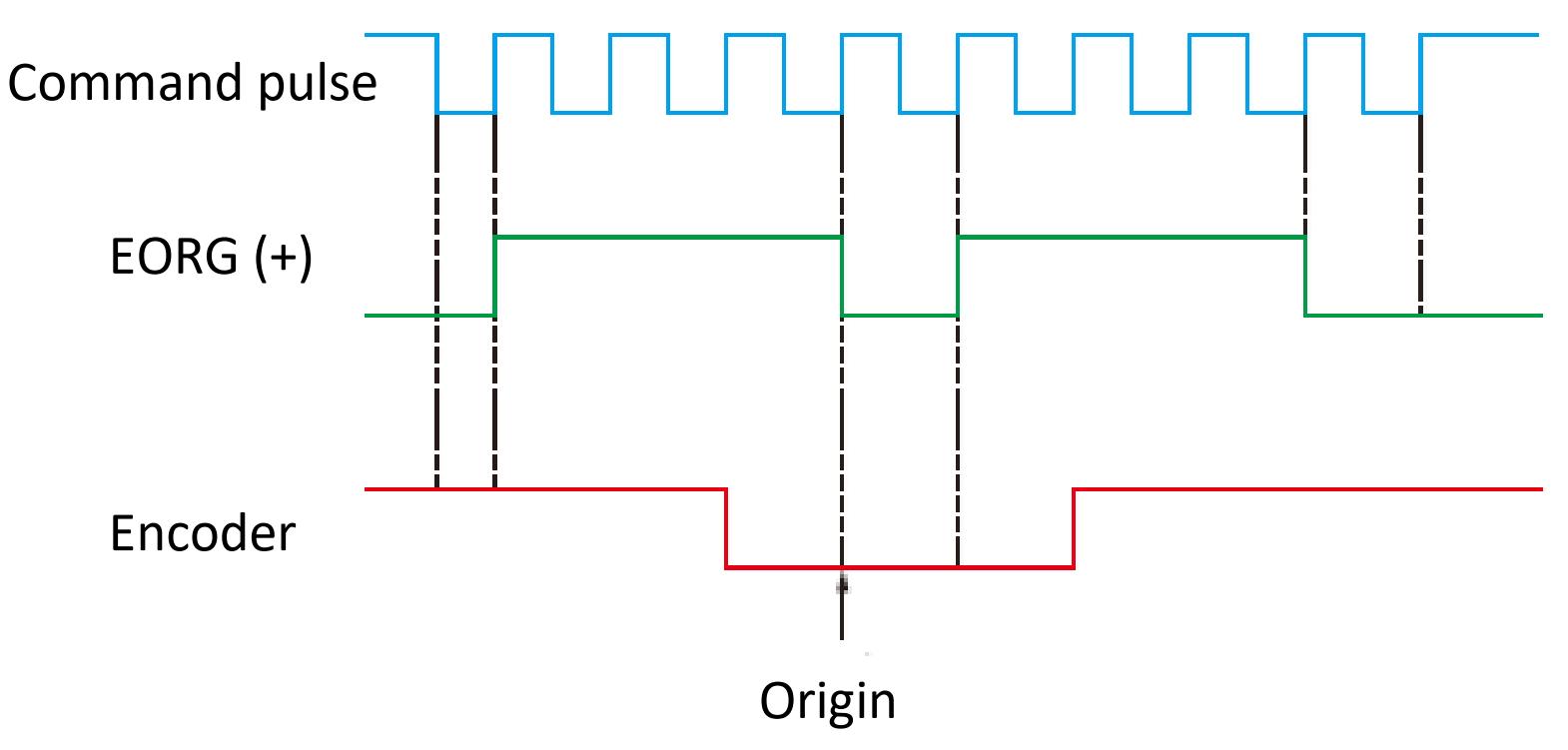
Figure 28 : Using the servo motor’s encoder signal in combination enables more reliable origin return operations
Software end-limit
You should set the software end-limits (soft limits) inside the hardware end-limits (hard limits), which are placed at the mechanical stage ends (Figure 29). The positions of the soft end-limits are managed by the main control to prevent the moves exceeding the values to move toward the hard end-limits.
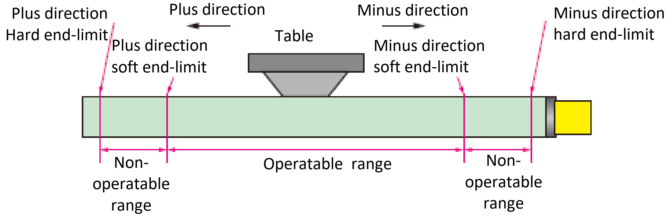
Figure 29 : Place the software end-limits inside the mechanical end-limits
Manual Pulse Generator
 Instead of writing programs for positioning control each time, a manual pulser device is a convenient tool to perform small manual movements or position alignment (Photo 1 and Figure 30).
A manual pulser incorporates an encoder within a rotary dial with graduations, and the operators of the pulser device rotates it while viewing the workpiece on the table for fine positioning. In the case of a stepping motor, it may go out-of-step if rotating quickly, so it is also important to suppress the speed.
The manual pulser is also referred to as a “Manual Pulse Generator”, abbreviated as MPG.
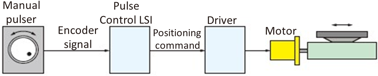
Figure 30 : Manual pulser allows fine movement by spinning a MPG wheel
Incremental position and Absolute position
Specifying an incremental position is to indicate how much you move an object from the current position of the motor as the reference point.
For example, suppose a motor is currently at a position of 1,000 pulses (or 1,000 steps). The command “Move +500 pulses in incremental position” causes the motor to advance 500 pulses, reaching a total of 1,500 pulses. In this case, no matter where the initial position is, the motor always moves the specified amount from the current position.
This drive method moves only a specific distance or angle. For example, it is used in conveyor systems that eject parts at regular intervals or in rotary stages that rotates only a specific angle.
Specifying an absolute position is to directly specify a specific target position within the entire operating range of a motor.
For example, suppose a specific target position is 3,000 pulses counted from the motor’s origin (reference 0 pulse position). Regardless of where the motor is currently located, if you command “Move to 3,000 pulses in absolute position,” the motor will always move to the position of 3,000 pulses.
To perform absolute position control, it is necessary to accurately determine the current absolute position of the motor. Therefore, when the system is powered ON or reset, it is always necessary to perform the origin return and reset the current position of the motor to 0 (or a specific reference value). When using an absolute encoder, the absolute position can always be determined, and the origin return may not be required.