2.5.1.1 Direction control
The JMAX[axis] command can be used to define the maximum analog input value for the specified axis. This parameter has units of millivolts (mV) and a range of 0 to 3300. This value will define the analog input value in which the maximum joystick speed occurs in the positive direction. This command is only available in ASCII mode.
Similarly, the JMIN[axis] command can be used to define the minimum analog input value for the specified axis. This parameter has units of millivolts (mV) and a range of 0 to 3300. This value will define the analog input value in which the maximum joystick speed occurs in the negative direction. This command is only available in ASCII mode.
MID represents the zero-joystick position. There is no command corresponding to MID. This is an internally calculated value using the following formula:

During joystick operation, analog input of JMIN[axis] to MID represents negative joystick direction and analog input of MID to JMAX[axis] represents positive joystick direction. Setting the value of JMAX[axis] to be less than the value of JMIN[axis] will result in a change of direction polarity during joystick operation.
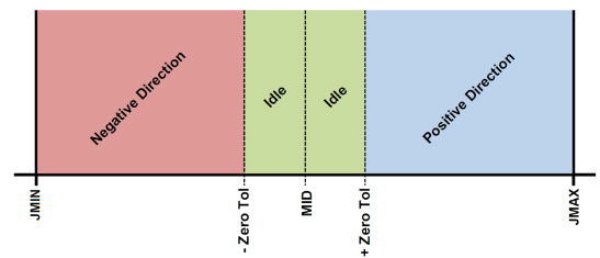
The ASCII command JTOL[axis] can be used to define the zero-tolerance (or dead) zone around the MID value. No movement will occur while the analog input value is within the zero-tolerance zone. This parameter has units of millivolts (mV) and a range of 0 to 3300. The zero-tolerance parameter will be on the positive and negative side of the MID point to define to the zero-tolerance zone. See the figure above for details.
Example: The zero-tolerance zone at JMAX = 3,250 mV, JMIN = 10 mV, JTOL = 50 mV will be
- 1580 mV ~ 1680 mV since ((3,250 – 10) ÷ 2) +10 = 1,630 mV
- 1,630 mV ±50 mV
|
ASCII |
|||
|
Standalone |
⎯ |
⎯ |
⎯ |
< Section Home | Home | Next SubSection >