IBI - Inverted Buffered input
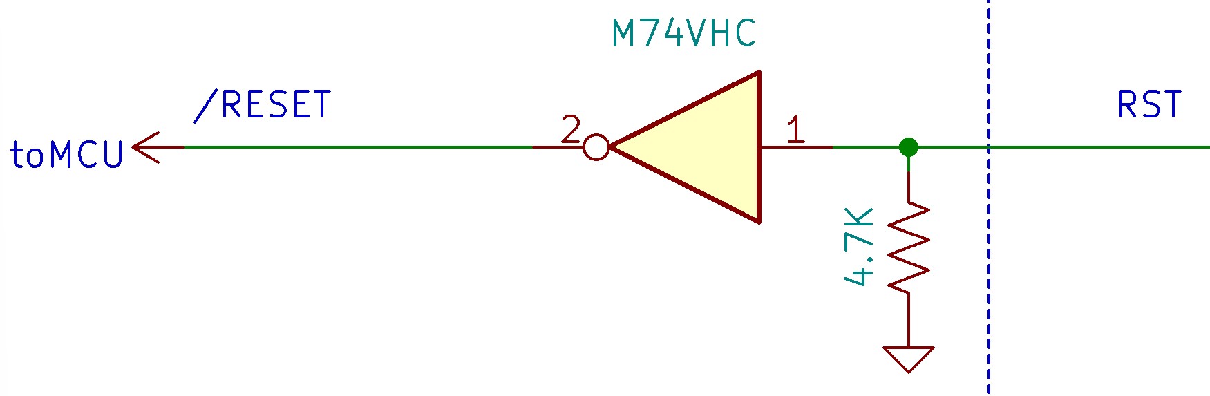
Below is the detailed schematic of the inverted buffered digital inputs.
Schematic:
Notes:
The inverted buffered digital inputs are designed to work with open collector (Sourcing) or TTL logic outputs. When connecting a TTL output, ensure the logic voltage is at least 5V.
When this digital input is pulled up (sourcing), current will flow from the external power supply through the internal 4.7K resister ground. Ensure that supply voltage is 48V or less and current is limited to 11mA or less.
To deactivate the input, the digital input should be left unconnected or switched back to ground.
Applies to:
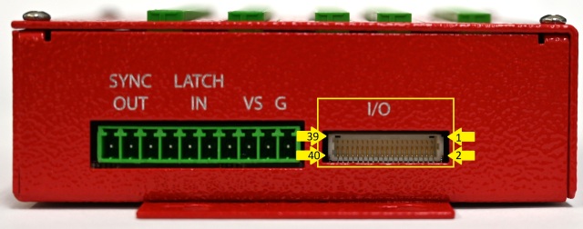
Reset input - 40-PIN DIO connector (I/O Expansion Connector) Pins 40