OI - Opto-isolated input
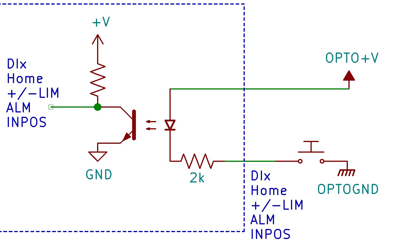
Below is the detailed schematic of the opto-isolated digital inputs. All opto-isolated digital inputs are NPN type.
Schematic:
Notes:
•The opto-supply must be connected to at least +12VDC, but not exceed +48VDC, in order for the opto-isolated digital inputs to operate.
•When a digital input is pulled to ground, current will flow from the opto-supply to ground, and the opto-isolator will then power on and activate the corresponding input(s).
•To deactivate the input, a digital input should be left unconnected or switched back to the opto-supply. This will stop current from flowing through the opto-isolator to ground.
Applies to:
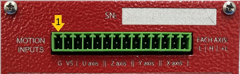
14-PIN Motion Input Connector Pin 3 to 14
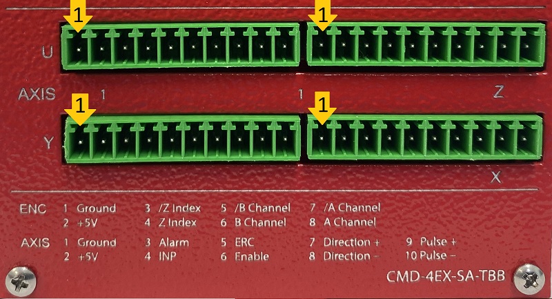
10-PIN TBB Axis Connectors Pins 3 and 4
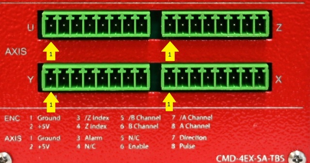
8-PIN TBS Axis Connectors Pins 3 and 4