
2.6 E-STOP input
This is the input for the mechanical (off PCB) E-Stop switch. When activated STO2 is activated. The E-Stop input pin must be connected to ISO+ for the controller to move the motors. Logic of E-Stop cannot be changed. E-Stop can also be triggered by the ESTOP command.
|
|
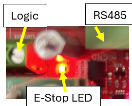
E-Stop, can be triggered by, removing ISO+ from E-STOP input, or sending the ESTOP command. The RED LED between the +12Vdc to +24Vdc (Logic Power) input, and the RS485 input will light when E-Stop is activated. If enabled by setting of JP1, GPDO3 will also activate when E-Stop is active. To clear an E-STOP reapply ISO+ to E-Stop input, and send the CLR command. https://support.nipponpulse.com/NPA_Command_Reference/POL-Polarity.html |
|
•+/- Limits for each axis These are the inputs for the mechanical (off PCB) end of travel limits. By default, the limit is triggered by connecting ISO- to the corresponding limit input. The signal is routed to the Commander and the MP3 servo driver. The logic can be changed, by the POL[AXIS] (bit3) command on the Commander, and the Input/Output settings of the MP3 servo driver. |
+/- Limits. By default, limits are active when ISO- is connected to the limit input. CMD POL[axis](bit3) = 1 MP3 IN 2,3,8,9,14,15 = Limit LO To activate limit when ISO- is removed from the limit input, change settings to: CMD POL[axis](bit3) = 0 MP3 IN 2,3,8,9,14,15 = Limit Hi https://support.nipponpulse.com/Commander/213111LimitSwitches.html https://support.nipponpulse.com/NPA_Command_Reference/POL-Polarity.html |
|
Home input By default, home input is active when ISO- is connected to the home input. CMD POL[axis](bit4) = 0 MP3 IN 4, 10, 16 = Home Active LO To activate limit when ISO- is removed from the home input, change settings to: CMD POL[axis](bit4) = 1 MP3 IN 4, 10, 16 = Home Active Hi https://support.nipponpulse.com/Commander/213113Homeswitch.html https://support.nipponpulse.com/NPA_Command_Reference/POL-Polarity.html |
Home input for each axis These are the inputs for the off PCB home input. By default, a home is triggered by connecting ISO- to the corresponding home input. The signal is routed to the Commander and the MP3 servo driver. The logic can be changed, by the POL[AXIS] (bit4) command on the Commander, and the Input/Output settings of the MP3 servo driver. |
STO theory of operation
When E-Stop is triggered:
Timing What Happens
0ms All Axis in motion decelerate to stop.
100ms All Motion commands to motor driver is stopped and motion cannot be started on all axis.
200ms Motor Power is removed from motor drive. Logic power is left on.
440ms All motor windings connected to pins 1 and 2 are disconnected from the drive.