3.10.1 Advanced Digital IO Screen
The advance Digital IO screen brings in additional configurable settings for Latch and Sync functions. Settings for digital input and output polarity and digital output status on power up are also available.
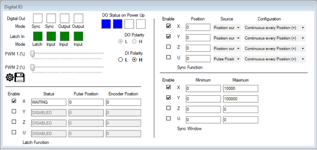
Digital output polarity (DOP) can be set to active low or high, and the status on power up (DOBOOT) can be set by clicking the desired status in the boxes. The digital input polarity (DIP) can also be set to active high or low. The status of the digital outputs (DO) can be changed by clicking the desired boxes.
Latch function can be set for each axis. Once the axis is enabled (LT), the Status will indicate the axis is WAITING. Once a digital input is triggered, the status (LTS) will indicated it has LATCHED, the Pulse (LTP) and Encoder (LTE) Position will be captured and displayed.
The Synchronization functions can be configured on the right-hand side of the screen for each axis. The top portion sets the synchronization configuration, while the lower portion enables and sets the range for the synchronization window. For each axis, the synchronization operation can be enabled (SYNO) or disabled (SYNF), the synchronization position point (SYNP), the source position counter (pulse position out or encoder in) and logic of the synchronization pulse of when it should trigger (SYNC). The source and configuration is set using the decimal equivalent of a 4 bit value.
SYNC[axis]=[value], with [value] equal to:
1 – Pulse position, trigger when sync position = actual position from any direction
2 – Pulse position, trigger when sync position = actual position from positive direction
3 – Pulse position, trigger when sync position = actual position from negative direction
4 – Pulse position, trigger when sync position > actual position
5 – Pulse position, trigger when sync position < actual position
8 – Pulse position, trigger continuous, any direction
9 – Pulse position, trigger continuous in positive direction
10 – Pulse position, trigger continuous in negative direction
17 – Encoder position, trigger when sync position = actual position from any direction
18 – Encoder position, trigger when sync position = actual position from positive direction
19 – Encoder position, trigger when sync position = actual position from negative direction
20 – Encoder position, trigger when sync position > actual position
21 – Encoder position, trigger when sync position < actual position
24 – Encoder position, trigger continuous, any direction
25 – Encoder position, trigger continuous in positive direction
26 – Encoder position, trigger continuous in negative direction
For configurations that trigger continuously (8, 9, 10, 24, 25, 16), the Synchronization window can be active over a range of positions. The Synchronization window can be enabled (SYNWO), or disabled (SYNWF) for each axis, and minimum and maximum position values set (SYNMIN, SYNMAX), for each axis.