Setting Driver Current
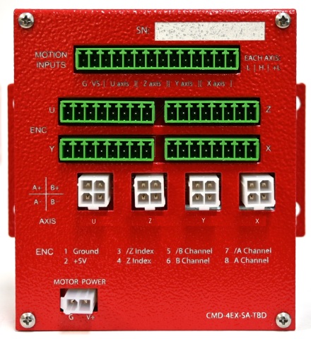
The CMD-4EX-SA-TBD was designed to work seamlessly with stepper motors supplied by Nippon Pulse. When ordering the CMD-4EX-SA-TBD, you can define the current settings for each axis to match the Nippon Pulse stepper motors you have selected. It is also possible to change the current settings at a later date.
The CMD-4EX-SA-TBD contains a series of jumpers to configure the driver current settings.
To set the current, follow these steps:
|
1.Disconnect all power and cables from the CMD-4EX-SA-TBD. |
|
|
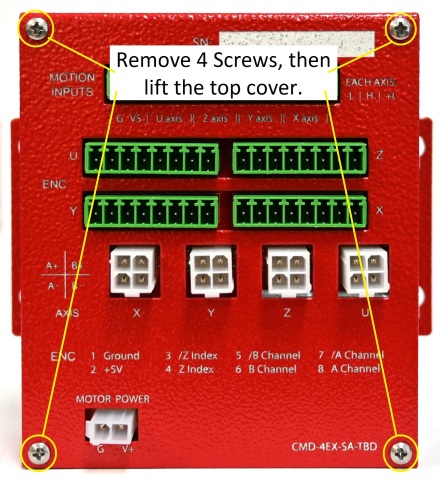
2.Remove the 4 screws from the top cover and lift the cover straight up. |
|
|
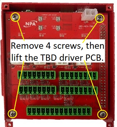
3.Remove the 4 screws from the TBD board, then lift the TBD board straight up. |
|
|
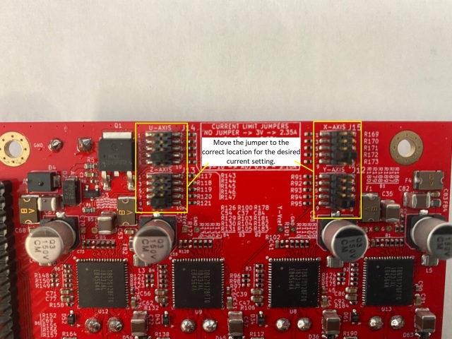
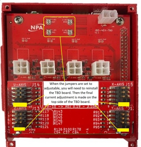
4.Flip the TBD board over, and you will see the jumpers on the edge closest to the power connector. |
|
|
5.Move the jumper to the location corresponding to the current setting needed. |
|
|
If none of the predefined current ranges will meet your needs, set the jumper to position 9,10 (ADJ) and use the potentiometer on the top of the TBD board to set the correct current. |
|
|
6.Reinstall the TBD board into the CMD-4EX-SA. Ensure the 58pin header is installed and seated correctly. Install the 4 screws to the TBD board. |
|
|
7.Verify that the 58pin header is mating correctly and that the TBD board is sitting flat on the standoffs. |
|
|
8.If you used a predefined current setting. Go-to step 16. |
|
|
9.If you need to set the driver to a current not predefined, calculate the required Vref value using the formula to the right: You can set Vref to any value between 0.24V and 2.68V. |
Vref = Iout / 0.78 |
|
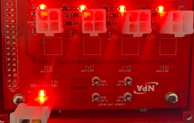
10.Connect 12Vdc to 24Vdc to the motor power in. The LED next to the power input connector and the LED next to each motor connector should light up. |
|
|
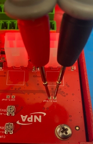
11.Set the voltmeter to DC voltage and to the proper scale (around 3 V). |
|
|
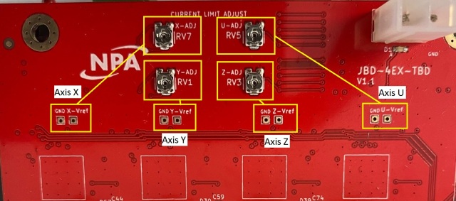
12.Place the voltmeter probes on the correct test points for the driver you will be setting. Black to GND test point and Red to Vref test point. |
|
|
13.Use a screwdriver to adjust the corresponding potentiometer to the value we calculated in step 9. |
|
|
14.Repeat steps 9 to 13 for each axis for which the current must be set. |
|
|
15.Remove the power and other cables from the CMD-4EX-SA-TBD. |
|
|
16.Install the top cover back on the CMD-4EX-SA-TBD, and install the 4 screws securing the cover. |
|