OPI - Opto Power Inputs
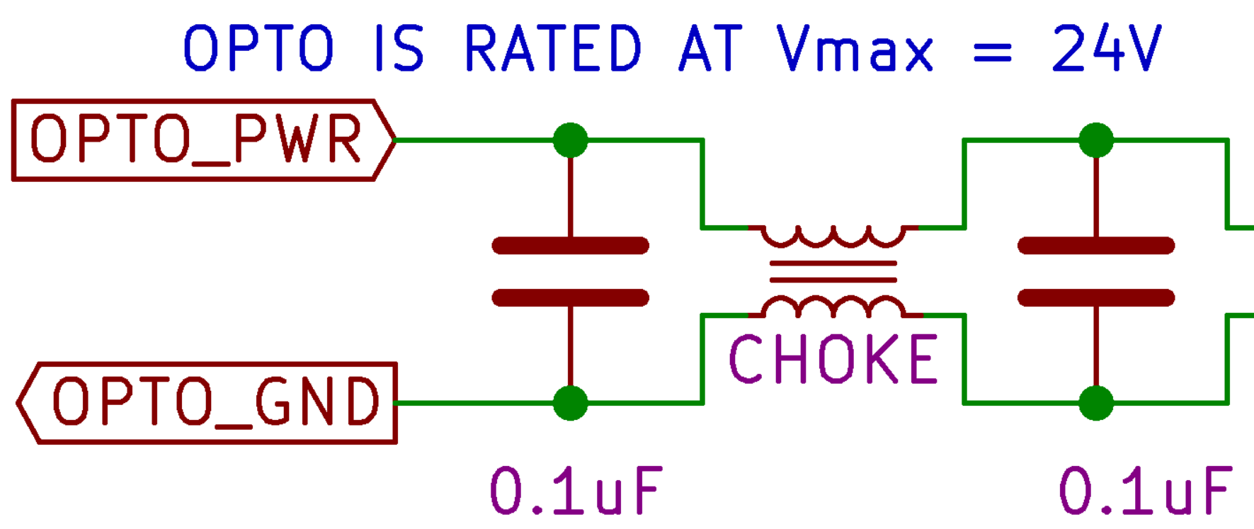
Below is the detailed schematic of the Opto-power input lines.
Schematic:
Notes:
The opto-power inputs are individuality filtered. +12 to +24 VDC. Ensure that opto-power voltage does not exceed 24VDC.
Applies to:
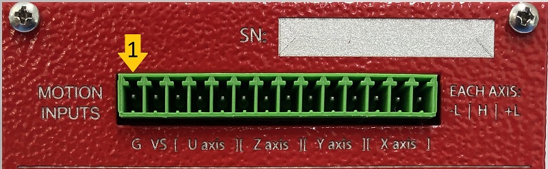
14-PIN Motion Input Connector Pin 1 and 2
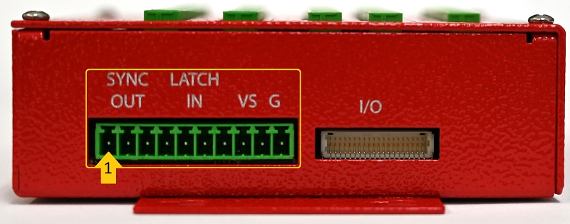
10-PIN DIO connector (High speed Input/Output) Pin 9 and 10
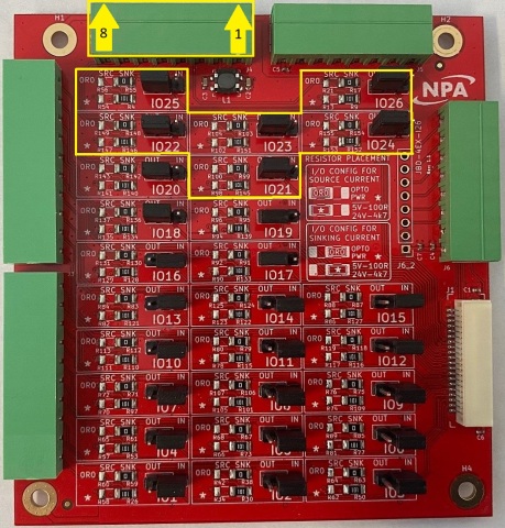
8-PIN J4 General I/O (21-26 Opto power) connector Pin 1 and 2