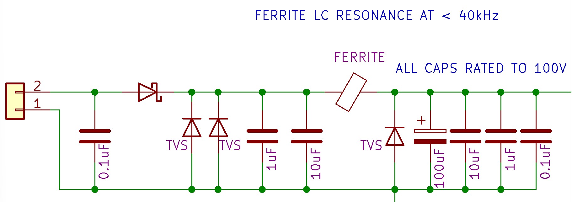
Below is the detailed schematic of the Logic Power input.
Schematic:
Notes:
•The logic power input was designed to operate between 12Vdc to 48Vdc. It offers ESD protection, Reverse voltage, Over-voltage/Transients, and current limiting.
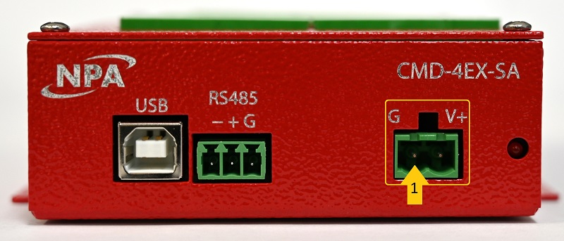
Applies to:
2-PIN Logic Power