
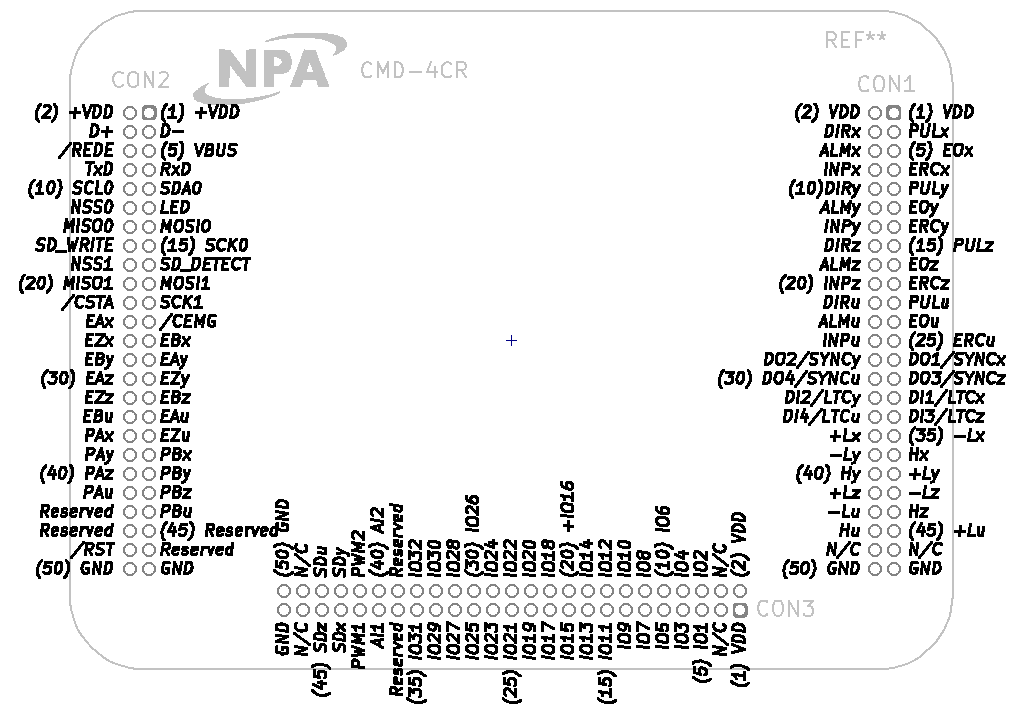
6.2.1.1 Pin Assignment Diagram
Viewed from the top, looking through the device (as laid out on PCB.)
Using CON1 as an example: pin 1 is on the top right, and pin 2 is next to it on the top left; then pin 3 is below pin 1, and on and on. This graphic shows pins 1 and 2, then includes the pin numbers of the multiples of five (5, 10, 15...) for ease of use.
< Section Home | Home | Next SubSection >