
Input Circuit
Input Circuit
On this page
Limit, Home, and Digital Inputs
Schematic of the opto-isolated limit, home, and general purpose digital inputs (All opto-isolated digital inputs are NPN type):
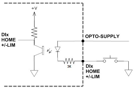
The opto-supply must be connected to +12 to +24VDC in order for the limit, home, and digital inputs to operate.
When the digital input is pulled to ground, current will flow from the opto-supply to ground, turning on the opto-isolator and activating the input.
To de-activate the input, the digital input should be left unconnected or pulled up to the opto-supply, preventing current from flowing through the opto-isolator.
Analog inputs are 0 to 5V range and 10 bit in resolution. Using two analog inputs, joystick control can be achieved. Section 7.15 will provide details on joystick control.
The maximum source current for the analog inputs is 10mA.
Both single-ended and differential quadrature encoder inputs are accepted.
When using single-ended encoders, use the /A, /B, and /Z inputs.
+5V supply and Ground signals are available to power the encoder. Make sure the total current usage is less than 200mA for the +5V.
The maximum encoder frequency is 5MHz.