
2.2.1.1 Pinout Diagrams
Pinout Overview
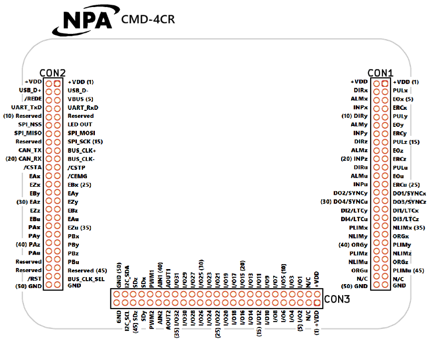
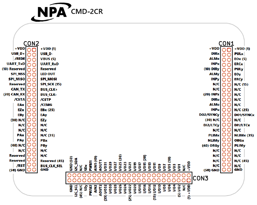
Pin numbering is viewed from the top, looking through the device (as laid out on the PCB).
Vertical connectors (CON1, CON2)
- Pin 1: Top right
- Pin 2: Top left (adjacent to pin 1)
- Pin 3: Below pin 1
- Continues sequentially downward
Horizontal connectors (CON3, CON4)
- Pin 1: Bottom right
- Pin 2: Top right (above pin 1)
- Pin 3: Left of pin 1
- Continues sequentially to the left
Multiples of five (5, 10, 15...) are marked on the graphic for reference.
Pin Reference Format
In documentation, pins are referenced by their connector number followed by their pin number:
- Example: Pin 22 on CON1 → 1-22
- Example: Pin 48 on CON3 → 3-48
Master Pinouts by Model

< Section Home | Home | Next SubSection >