
2.9 Encoder Input Connection
Encoder [Feedback] inputs (X, Y, Z axis)
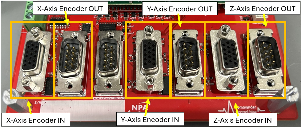
Each axis (X, Y, and Z) has an Encoder input, and an Encoder output. The output is buffered by a 74LVC07A or equivalent Hex buffer from the input encoder digital incremental signal.
Pin outs
|
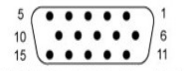
Encoder IN Incremental: DBHD-15 Digital Incremental Encoder Pin 1 – A+ Pin 2 – A- Pin 3 – B+ Pin 4 – B- Pin 5 – Z+ Pin 6 – Z- Pin 7 – 5V Pin 8 – 0V (gnd) Pin 9 – 15 – N/C |
Absolute: DBHD-15 SSI Pin 1 – Dat Pin 2 – /Dat Pin 5 – Clk Pin 6 – /Clk Pin 7 – 5V Pin 8 – 0V (gnd) Pin 9 – sin+ Pin 10 – sin- Pin 11 – cos+ Pin 12 – cos- Pin 3 – 4 & 13 - 15 – N/C |
|
Analog Incremental Encoder Pin 9 – sin+ Pin 10 – sin- Pin 11 – cos+ Pin 12 – cos- Pin 7 – 5V Pin 8 – 0V (gnd) Pin 1 – 6 & 13 - 15 – N/C |
EnDat Pin 1 – Dat Pin 2 – /Dat Pin 5 – Clk Pin 6 – /Clk Pin 7 – 5V Pin 8 – 0V (gnd) Pin 3 – 4 & 9 - 15 – N/C |
|
Digital Hall Effects Pin 13 – Hall V Pin 14 – Hall W Pin 15 – Hall U Pin 12 – cos- Pin 7 – 5V Pin 8 – 0V (gnd) Pin 1 – 6 & 9 - 12 – N/C |
Absolute A Pin 1 – SD+ Pin 2 – SD- Pin 7 – 5V Pin 8 – 0V (gnd) Pin 3 – 6 & 9 - 15 – N/C |
|
|
BiSS (B&C) Pin 1 – SL+ Pin 2 – SL- Pin 5 – MA+ Pin 6 – MA- Pin 7 – 5V Pin 8 – 0V (gnd) Pin 3 – 4 & 9 - 15 – N/C |
|
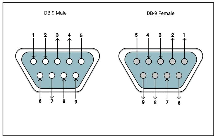
Encoder Out - Incremental Pin 1 – Z- Pin 7 – Z+ Pin 2 – A- Pin 6 – A+ Pin 3 – B- Pin 8 – B+ Pin 5 – gnd Pin 4 & 9 – N/C
|
|
Motor Out
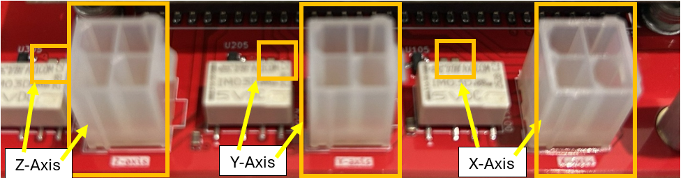
Motor winding Pinout

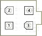
Stepper
Pin 1 – A Pin 3 – /A
Pin 2 – B Pin 4 – /B
Servo
Pin 1 – V Pin 3 – W
Pin 2 – U Pin 4 – N/C
Drive status:
AMP LEDS Next to Motor phase connections
The two LEDs show the states of each axis of the MP3 by changing color, and either blinking or remaining solid.
The possible color and blink combinations are:
• Green/Solid: Drive OK and enabled. Will run in response to input commands.
• Green/Slow-Blinking: Drive OK but NOT-enabled. Will change to Green/Solid when enabled.
• Green/Fast-Blinking: Positive or Negative limit switch active. Drive will only move in direction not inhibited by limit switch.
• Red/Solid: Transient fault condition. Drive will resume operation when fault is removed.
• Red/Blinking: Latching fault. Operation will not resume until drive is Reset.