
2.3 Digital Outputs
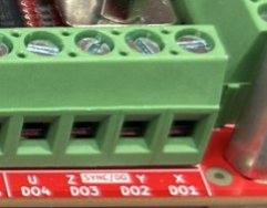
4 high speed opto-isolated outputs (Isolated (ISO-) ground), used for Sync or digital output.
Logic level signal (+5V) referenced from ISO-
|
|
X (DO1) Y (DO2), Z (DO3), and U (DO4) are 5V referenced from ISO-. Controlled by the DO command or by the SYNC function. https://support.nipponpulse.com/NPA_Command_Reference/DO-DigitalOutputStatus.html https://support.nipponpulse.com/NPA_Command_Reference/SYNC-SynchronizationMode.html |
|
|
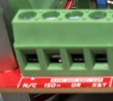
OR output LOW if all SYNC/DO are low, otherwise HIGH (5V referenced from ISO-) X&Y output of DO1(X sync) and DO2(Y sync) output inverted, LOW when both X, Y HIGH, otherwise HIGH (5V referenced from ISO-) |
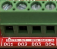
4 GPDO (GPDO 1-4) opto-isolated output (Isolated (ISO-) ground), used for General purpose outputs.
Open-drain outputs referenced from ISO-
|
|
GPDO1 (DO1) GPDO2 (DO2), GPDO3 (DO3), and GPDO4 (DO4) are open-drain referenced from ISO-. Controlled by the IO command. IO21 GPDO1 IO23 GPDO2 IO25 GPDO3 IO27 GPDO4 |
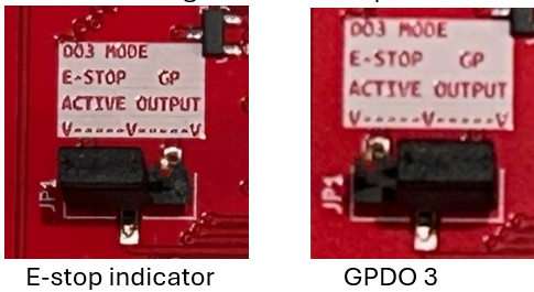
GPDO3 is configurable as E-stop indicator or GPIO by changing the position of the shorting jumper on JP1.
|
|
GPDO3 (DO3) can be enabled by the IO command or by the E-Stop input and ESTOP command, depending on the placement of JP1. |
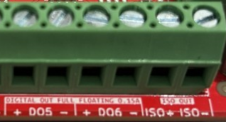
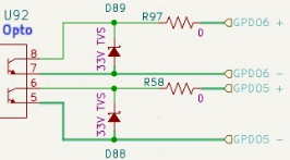
2 GPDO (GPDO 5,6) floating opto-isolated outputs (No ground reference)
|
|
|
|
Both legs of the optocouplers collector are exposed, no current limiter. This allows the GPDO to be configured by the user as sink or source output.
|
GPDO5 (DO5), and GPDO6 (DO6) are floating opto-isolated outputs. Ensure a properly sized current limit resistor, allowing 1-10mA is in line with the output. Controlled by the IO command. IO29 GPDO5 IO31 GPDO6 |
3 mechanical contact (Relay) outputs (No ground reference). Contact rated for 15A 250Vac/28Vdc
|
|
MC1, MC2, and MC3 are relay contact outputs. Controlled by the RLY command. 0 open, 1 closed. MC1 RLY1 MC2 RLY2 MC3 RLY3 |
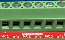
Since this is a relay contact output there is no restriction on polarity or need for a current limit resistor. Ensure load does not exceed the contact rating of 15A 250Vac/28Vdc.
Use the RLY[port] command to change the relay outputs, with 0 for an open relay and 1 for a closed relay. Example: RLY1, reads the state of relay 1 (MC1) and RLY2=1, closes the contacts of relay 2 (MC2).