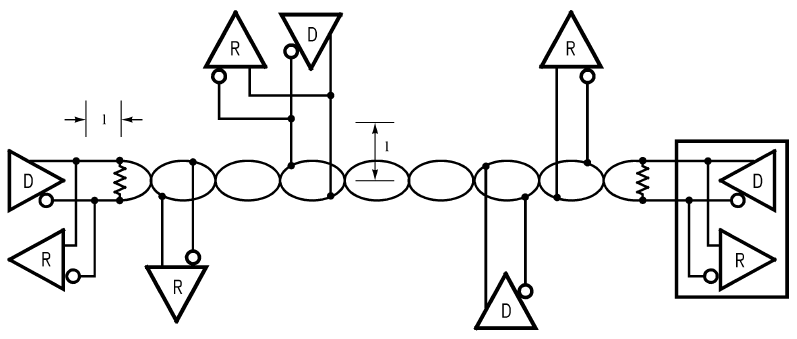
Typical RS-485 Setup
An RS-485 bus supports two-way data transfer over a single pair of wires. While RS-485 can be used as a point-to-point bus, a typical bus includes multiple nodes (up to 32). Each transceiver includes a differential driver (D) and a differential receiver (R). The stub length is I. The bus is terminated only at the ends — not at each node.
 .
.
 Bus configuration
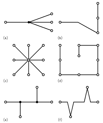
Because RS-485 allows connecting multiple transceivers, the bus configuration is not as straightforward as in a point-to-point bus (RS-232C, for example). In a point-to-point bus, a single driver connects to one receiver alone. The optimal configuration for the RS-485 bus is the daisy-chain connection from node 1 to node 2 to node 3 to node n. The bus must form a single continuous path, and the nodes in the middle of the bus must not be at the ends of long branches, spokes, or stubs. See the figure to the right, Figure a, Figure c, and Figure e illustrate three common but improper bus configurations. (If you mistakenly use one of these configurations, you can usually make it work but only through substantial effort and modification.) Figure b, Figure d, and Figure f show equivalent daisy-chained configurations.
Connecting a node to the cable creates a stub, and, therefore, every node has a stub. Minimizing the stub length minimizes transmission-line problems. For standard transceivers with transition times around 10 ns, stubs should be shorter than 6 in. A better rule is to make the stubs as short as possible. A "star" configuration (Figure c) is a special case and a cause for concern. This configuration usually does not provide a clean signaling environment even if the cable runs are all of equal length. The star configuration also presents a termination problem, because terminating every endpoint would overload the driver.
Terminating only two endpoints solves the loading problem but creates transmission-line problems at the unterminated ends. A true daisy-chain connection avoids all these problems.
Bus termination
There are several options for terminating an RS-485 bus. The first option is no termination, which is feasible if the cable is short and if the data rate is low. Reflections occur, but they settle after about three round-trip delays. For a short-cable, the round-trip delay is short and, if the data rate is low, the unit interval is long. Under these conditions, the reflections settle out before sampling, which occurs at the middle of the bit interval.
The most popular termination option is to connect a single resistor across the conductor pair at each end. The resistor value matches the cable's differential-mode characteristic impedance. If you terminate the bus in this way, no reflections occur, and the signal fidelity is excellent. The problem with this termination option is the power dissipated in the termination resistors.
If you must minimize power dissipation, an RC termination may be the solution. In place of the single resistor, you use a resistor in series with a capacitor. The capacitor appears as a short circuit during transitions, and the resistor terminates the line. Once the capacitor charges, it blocks the DC loop current and presents a light load to the driver. Low-pass effects limit use of the RC termination to lower data-rate applications.
Another popular option is a modified parallel termination that also provides a fail-safe bias. A detailed discussion of fail-safe biasing occurs later in the article. Figure 5 compares the four popular termination methods. The main point to remember is that, if you use termination, you should locate the termination networks at the two extreme ends of the cable, not at every node.
The CMD-4EX-SA has a built in RC Termination and uses 120.
For more information on how to setup and bulletproof your RS-485 network, please reference AN-1057 from Texas Instruments. The information in this section was referenced from this white-paper.
< Previous Chapter | Topic Home | Home | Next Topic >