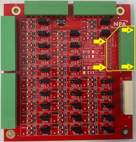
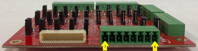
8-PIN J6 Analog In/Out J6_2 (Joystick) connector
Pin description:
|
Pin # |
In/Out |
Name |
Description |
I/F circuit |
|
1 |
O |
VCC |
Power Output +5 Vdc |
|
|
2 |
O |
GND |
Ground |
|
|
3 |
I |
AIN1 |
Analog in 1 |
|
|
4 |
I |
AIN2 |
Analog in 2 |
|
|
5 |
O |
AOUT1 |
Analog output 1 |
PWM to Analog RC |
|
6 |
O |
AOUT2 |
Analog output 2 |
|
|
7 |
N/C |
N/C |
Reserved |
|
|
8 |
N/C |
N/C |
Reserved |
|
Note:
Limit the current out from all VCC (+5Vdc) output to 250mA.
Analog out is controlled using the PWM[1-2] command. PWM1 controls AOUT1, PWM2 controls AOUT2.
J6_2 is used for Joystick connection.
Mating Connector
J6
Description: 8 pin 0.138" (3.5mm) connector
Manufacturer: On-Shore
Manufacturer Part: OSTTJ0811530
NPA part number: 430-408-10
Note: Other 3.81mm compatible connectors can be used.
J6_2
Description: 8 pin 0.1" (2.54mm) header
Note: Any 2.54mm compatible header can be used.