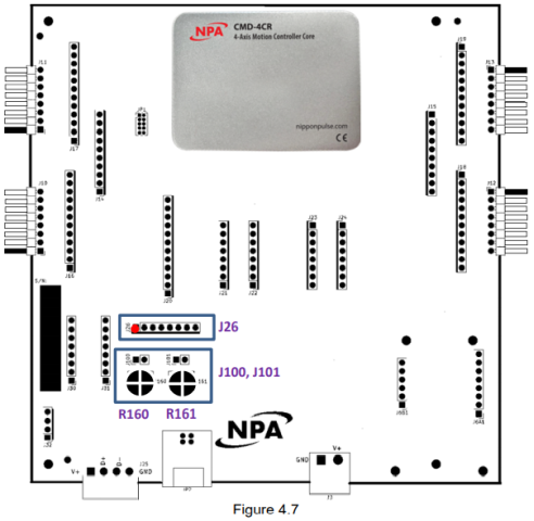
4.8 [J26] 8-Pin Analog Input Connector (2.54mm)
|
Pin # |
In/Out |
Name |
Description |
Interface |
|
1 |
O |
VDD |
+3.3V (VDD3) |
|
|
2 |
O |
GND |
Ground |
|
|
3 |
I |
AI1 |
Analog Input 1 (AI1) |
|
|
4 |
I |
AI2 |
Analog Input 2(AI2) |
|
|
5 |
NC |
NC |
Reserved |
|
|
6 |
NC |
NC |
Reserved |
|
|
7 |
O |
PWM1 |
PWMOUT1 |
|
|
8 |
O |
PWM2 |
PWMOUT2 |
|
|
Molex Pins - 0008550101 |
Molex Connector Housing - 0022013087 |
|
||
|
8 position cable with Molex connector: Z3-210-238-01 |
||||
There are on board potentiometers available to control AI1 and AI2. Potentiometer R160 is reserved for AI1 and R161 is reserved for AI2. In order to use the potentiometer, close jumper J100 and J101 to route AI1 and AI2 respectively.