
2.1 Power inputs and Status LEDs
Logic ground
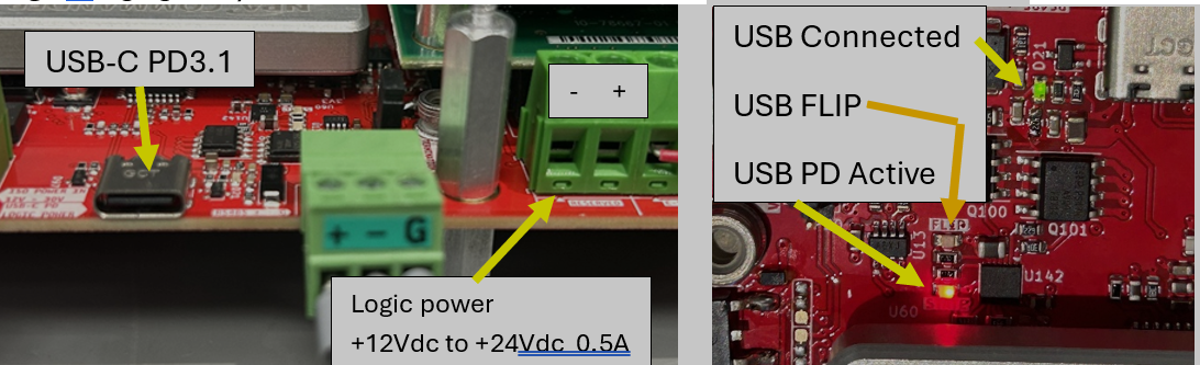
Note: NP-Link not available on this version (V2.0)
For V2, USB PD has been disabled and the logic power must be supplied to the Logic power +12Vdc to +24Vdc input.
 Do not exceed 24V on the Logic power +12Vdc to +24Vdc input at any time.
When the USB is connected the USB Connect LED will come on but the Flip and PD Active LEDs will stay off.
|
|
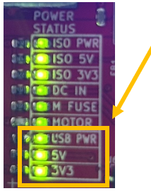
Power Status LED for Logic Power: USB PWR - NP-Link power, USB PD or “+12Vdc to +24Vdc” power inputs are active. 5V - 5V regulator is active. Used for U-axis out and pull up for inputs. 3V3 - 3.3V regulator is active. Used for Commander. |
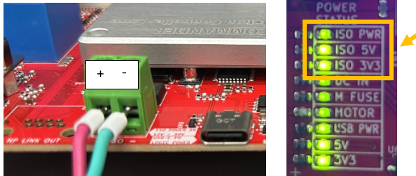
Isolated power for all I/O: (Isolated (ISO-) ground)
|
|
Power Status LED for Isolated power ISO PWR - “+12Vdc to +24Vdc” isolated power input is active. ISO 5V - 5V regulator is active. Used for Sync/DO outputs and DO1 to DO4 outputs. ISO 3V3 – iso 3.3V regulator is active. Used for NP-Link CAN output. |
Motor Power: (Logic ground)
|
|
Power Status LED for Motor Power DC IN “+24Vdc to +48Vdc” power input is active. M Fuse – Fuse for motor power is good. Motor – Power to Drive is active. If off check E-Stop is not active. |
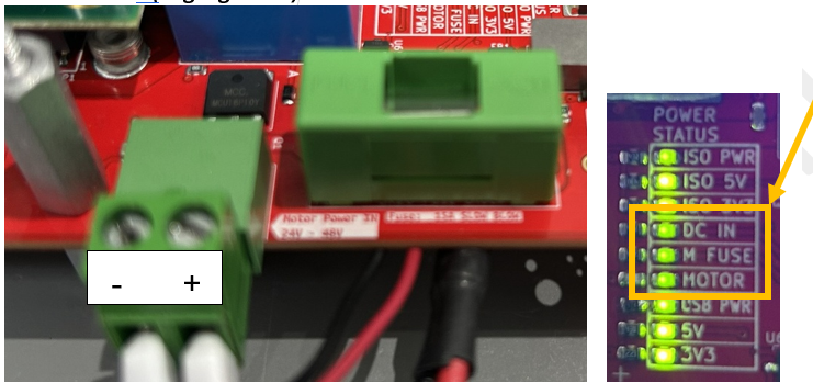
+24Vdc to +48Vdc
Mating connector: TERM BLOCK PLUG 2POS 5.08MM MFG: On Shore Technology PN: EDZ950/2