MODELNEW
"NEWMODEL 3DPrimitiveString"
This command creates a new object model using a 3D Primitive definition string to define it.
3DPrimitiveString - is an 3D Primitive definition string
The follow characters will be purged from the string:
CHR$(10)
CHR$(13)
CHR$(27)
CHR$(9)
CHR$(15)
CHR$(0)
CHR$(1)
Space
|
This allows you to define Model strings in normal text editor and the CRLF's, etc will be ignored.
You can define multiple models with one command string. Each Model is separated by its name definition which is between the < > characters. 3D primitive strings should not be larger than 32KB in size. The control will convert the string to binary format internally. You can later save that binary format in an EZ3P file format.
A 3D primitive defintion string always must start with the name of the Model for adding it to the Model Object List, which is an alphanumeric string between the < > characters.
ie.
"<MYMODEL>"
The Model name must be 8 or less characters (alphanumeric). The control will convert the name into an internal binary format for faster access. Model names are not case sensitive.
Next you define the properties of the 3D primitive model.
In designing the 3D primitive model, assume the Scenes (world) size is 200 x 200 x 200 units in size. The origin of the world is coordinate 0,0,0. The X axis goes from -100 to +100 (left to right). The Y axis goes from -100 to +100 (bottom to top). The Z axis goes from -100 to +100 (back to front). This means you have 100 units on each side (in all directions) of the origin. It is important to center your 3D model on the original since the objects rotation is based on this origin. Now you can offset the model from the origin if you want it to appear to be rotating around its own origin at distance (ie. think of the moon rotating around the earth. The moon would be offset from the origin which is the center of the earth).
The control 3D Objects have two scale factors. One is the objects independent scale factor and the other is a scene scale factor. They are combined when drawing the object. A model can have its own independent scale factor, but multiple objects which use the same model can have their own scene scale factors so they can be different sizes.
When the model is defined, independent scale factoring can be defined by changing the world coordinates in the models definition. World scaling is also useful in converting to a coordinate system larger than the standard 200 x 200 x 200 world coordinate system.
The 3D Primitive definition commands are all a single character in curly brackets.
ie.
{W}
Command parameters are always defines within parentheses ( ).
Characters not within parentheses ( ) will be be ignored. Values within a parameter, if there are multiple values, will be separated by a comma.
ie.
{W}(#,#,#)
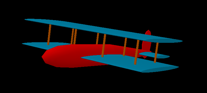
Some examples of 3D Primitive model command strings. Each command is on a separate line to make easier to read. All the commands would be sent together as one string and need not be separated by any other characters. You can though use a CR or CRLF between commands and they will be removed before processing the command list. An image of what the 3D primitive looks like (rotated in 3D space so you can what it really looks like) comes after each script. The 3D Primitive model only defines the basic shape of the model. Colors and other attributes are defined with the OPENGL Scripting language commands. Characters in gray (ie. 9 ) below are simply ignored (removed) by script engine.
<MYMODEL1>
{P}
1(-100,100,100)2(100,100,100)
3(-100,-100,100)4(100,-100,100)
5(-100,100,-100)6(100,100,-100)
7(-100,-100,-100)8(100,-100,-100)
{M}(1){Q}(1,5,7,3)
{M}(1){Q}(2,4,8,6)
{M}(1){Q}(5,1,2,6)
{M}(1){Q}(7,8,4,3)

<MYMODEL2>
{P}1(-100,100,100) 2(100,100,100)
3(-100,-100,100) 4(100,-100,100)
5(-100,100,-100) 6(100,100,-100)
7(-100,-100,-100) 8(100,-100,-100)
{M}(1){Q}(1,5,7,3)
{M}(2){Q}(2,4,8,6)
{M}(3){Q}(5,1,2,6)
{M}(4){Q}(7,8,4,3)
<MYMODEL3>
{P}1(-75, 40,-200) 2(-75, 40,200) 3(-75, 40,0)
4(-75,-30,-200) 5(-75,-30,200) 6(-75,-30,0)
7(100,-30,0) 8(-100,-30,0) 9(-180,-30,0)
10(190,0,0) 11(-120, 5,150) 12(-120, 5,-150)
13(-20, 5,150) 14(-20, 5,-150) 15(-120, 5,50)
16(-120, 5,-50) 17(-20, 5,50) 18(-20, 5,-50)
19(175,-30,-75) 20(175,-30,75) 21(175,-30,0)
WINGS:
{W}(1,.05,1)
{M}(1)
{C}(100,100,30,10,400,3)
{X}(1){D}(100,0,30,10,1)
{X}(0){D}(100,0,30,10,2)
{C}(100,100,30,10,400,6)
{X}(1){D}(100,0,30,10,4)
{X}(0){D}(100,0,30,10,5)
TAIL:
{W}(.5,.05,1)
{C}(100,100,30,10,150,21)
{X}(1){D}(100,0,30,10,19)
{X}(0){D}(100,0,30,10,20)
FUSELAGE:
{M}(2)
{W}(.5,.6,1)
{X}(2){C}(50,10,30,10,250,7)
{X}(2){C}(50,50,30,10,150,8)
{X}(0)
{W}(2,.6,.5)
{S}(50,12,12,9)
RUDDER:
{W}(.6,1,.1)
{S}(50,12,12,10)
WING STRUTS:
{W}(1,1,1)
{X}(4)
{M}(3)
{C}(3,3,6,6,78,11)
{C}(3,3,6,6,78,12)
{C}(3,3,6,6,78,13)
{C}(3,3,6,6,78,14)
{C}(3,3,6,6,78,15)
{C}(3,3,6,6,78,16)
{C}(3,3,6,6,78,17)
{C}(3,3,6,6,78,18)